Leeham News and Analysis
There's more to real news than a news release.

 Leeham News and Analysis
- Boeing unlikely to meet FAA’s 90-day deadline for new safety program April 18, 2024
- Focus on quality not slowing innovation, says GKN April 18, 2024
- Boeing defends 787, 777 against whistleblower charges April 17, 2024
- Dissecting Boeing CEO’s statement next new airplane will cost $50bn April 15, 2024
- Bjorn’s Corner: New engine development. Part 3. Propulsive efficiency April 12, 2024
Bjorn’s Corner: Turbofan engine challenges, Part 4

By Bjorn Fehrm
November 18, 2016, ©. Leeham Co: In our series on modern turbofan airliner engines, we will now go deeper into the compressor part. Last week, we covered the fundamentals of compressors. As compressors and turbines use the same principles, we also covered the fundamental working principles of turbines.
We also described that compressors are temperamental parts, which can protest to wrong handling with violent “burps” (burst stalls with the combustion gases going out the front of the engine) or end up in a rotating stall where it simply stops working.

Figure 1. Stylistic cross section of a two shaft turbofan with both axial and radial compressor. Source: GasTurb.
Turbines, on the other hand, are your robust companions. Aerodynamically they just work, albeit more or less efficiently dependent on what one asks them to do (mechanically it can be very different; we recently saw a turbine disintegrate with large consequences on an American Airlines Boeing 767 in Chicago). More on the turbines later.
In the GasTurb cross section of a two shaft turbofan in Figure 1, the engine has both an axial and a radial compressor. We will consider why engine designers combine these two for certain engine types.
Deeper dive into compressors
Compressors are divided into the two types which are common: axial compressors, which predominate by larger engines, and radial compressors, which are common for smaller engines.
The dominance of the axial compressor for larger engines is because it can conveniently be stacked stage by stage to achieve the pressure gain which is needed. Today’s design target for long range engines is 60:1 pressure ratio at Top of Climb (ToC) with minimum dimensions and weight. Each stage gains around 1.3:1 in pressure ratio for such engines.
Radial compressors gain more per stage, up to 6-8:1 per stage, but are difficult to cascade. The compressor accelerates the air along the impellers radial vanes, Figure 2. The air speed can be close to the speed of sound when it enters the diffusor to be slowed down and gain pressure.
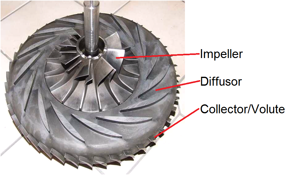
Figure 2. Radial compressor of the Solar T62 helicopter/APU engine. Source: Google images.
The collector or Volute then ducts the gas in the axial direction again, often to a reverse flow combustion chamber as seen in Figure 1.
Figure 3 is a cut through of the Safran Silvercrest engine for the new Dassault and Cessna mid-size business jets. It’s a top, modern engine in the 11,500lbf thrust class. It contains all the compressor types which are used in modern turbofans. We will therefore use it to go through each type and their characteristics.
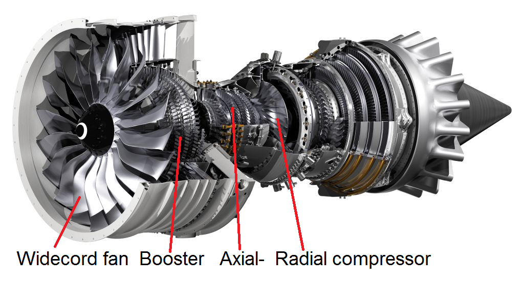
Figure 3. Safran Silvercrest biz. Jet engine with its different compressor types. Source: Safran.
The engine has a titanium wide cord fan followed by a booster axial compressor. It’s called a booster because its sitting on the same shaft as the fan and therefore rotates at a relatively low speed. The pressure gain is therefore modest; it “boosts” the rest of the compressor chain.
Booster blades are most often mounted on a prolonged fan hub. The booster blades have tangential speeds which are the same as the inner part of the fan. As the pressure gain in a compressor stage is achieved by diffusing air which has been accelerated in the blade section and the booster blades have a low tangential speed (we can assume a 4,000 RPM shaft speed; a 0.3m blade tip radius giving a blade tip speed of M0.37 or 125m/s), booster stages have very low pressure gains, around 1.10 to 1.15 per stage. The booster on the Silvercrest is four stages and would probably deliver a pressure gain of around 1.6-1.8.
The next compressor is the four stage high pressure axial compressor with a 20,000 RPM shaft speed. The compressor radius and shaft RPM is optimized for a high axial and radial compressor pressure gain. We can assume the four stage axial unit to have a gain of around 2.5 and the radial unit of around 6. Total pressure gain of inner part of fan, booster, axial and radial high pressure stages is 38.5:1 at ToC (Top of Climb, the aerodynamically most demanding point for a turbofan, where the compressor spins the fastest).
Why finish with a radial stage?
As an axial compressor compresses the air, the density increases and the air takes less place. To keep the axial speed around M0.5, the compressor duct gets narrower and the blades shorter, Figure 4.
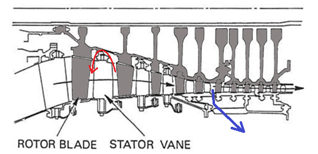
Figure 4. Typical axial compressor with 10 stages, variable vanes and bleed valve. Source: Rolls-Royce The jet engine.
As blade dimension shrinks, the leak losses around the tips increases. Blade tip clearances don’t scale with dimensions. At one point, the dimensions get too small for an efficient axial stage. The radial compressor does not have dimensional constrains in the same way and is therefore suited as the last compressor stage for smaller engines.
The diffusion for a radial compressor takes place at a large radius (Figure 2). It requires quite a swan neck duct to get the air collected at the center for an additional radial stage. Cascaded radial compressors are therefore seldom seen. It’s normal for the collector of a radial stage to route the air axially at constant radius to the start of a reverse flow combustion chamber. This is also true for the Silvercrest.
Seals and compressor stability
The axial stages for the high pressure compressor for the Silvercrest are milled from solid billets of titanium, so-called Blisks (Bladed disks). Blisks avoid the air leak path around the blades fixing on the rotor, thereby gaining efficiency.
Other leakage paths in Figure 4 are from the downstream side of a stator vane around the vanes seal with the rotor drum and back to the area before the vane (red path). This forces every stage to have rotating seals between the static vanes and the rotating rotor drum. Rotating seals that seal well for the 10,000 to 20,000 missions that modern airliners fly before engine overhaul is challenging technology.
Another tricky area is the compressors function at different RPMs. At close to the design point, i.e., at ToC, cruise and takeoff, the flow through the compressor is as planned. When reducing the thrust, the compressor spins slower and the axial speed of the flow reduces. The flow axial speed in the rear stages is kept up by the air not being so compressed; it takes more space and the speed in the narrow duct increases.
At the front of the compressor, the lower RPM slows the axial speed of the air and there is no significant change in compression. As described in the last Corner, the lower axial air speed means higher angles of attack for the front rotor blades and these approach stall.
There are three ways to counter this:
- Bleed away air at the compressor mid-point, thereby increasing the flow in the compressor front stages (blue arrow). This is called using a compressor bleed valve. You can see two so called “Handling bleed” paths for the compressors in Figure 1.
- Change the direction of incoming air to the front stages with variable angle stator vanes, so that the angle of attack reduces. In Figure 2, the first four stages have variable angle vanes.
- Make the compressors shorter so that the duct dimensions don’t vary so much. This is one reason for dividing compressors into shorter low and high pressure compressors on two different shafts with only aerodynamic coupling between the compressors.
In practical engines, all these methods are used in unison to make the fickle compressors behave over a wide range of RPMs and therefore thrust settings.
Compressor temperatures
The front of the compressor sees temperatures of the air flow after the fan. The temperature after the fan is around 25°C hotter than the intake temperature. As the stages pass, the air gets hotter until it can no longer be handled by the preferred material for Blisks, titanium. This means that the last stages in the compressor must be made of temperature-resistant Inconel or other super alloys.
For today’s high pressure engines, the temperature at the last compressor stages is on the limit for what can be handled with the materials available today. Just like the entry temperature to the turbine can be a limiter for engine performance, the so-called T3 temperature, Figure 1, can also limit the engines performance. T3 is approaching 700°C for the most modern long range engines at takeoff thrust on a hot summer day.
Unlike for combustor/turbines, there is no way to cool the compressor by routing cooling air into the blades, because there is no air available with lower temperature at the high pressure required. It’s possible to cool the compressor air via a pre-cooler heat exchanger protruding into the cold fan stream. This is looked at for the next generation engines.
thanks for the explaining the design trades between axial and centrifugal compressor stages.
I would think modern 3d aero CFD could be used to mitigate some of the packaging issues that make use of multiple centrifugal stages challenging while greatly improving the stage efficiency. 2 centrifugal stages at 8:1 each would give a 64:1 total pressure ratio, I have to believe the reduction in complexity, part count and weight would be hard to argue with.
Fig 2 above looks like a pretty primitive example compared to modern axial blade geometries
A diagonal compressor ?
Its used in Pratt & Whitney Canada PW600 series small turbofan
I think the 8:1 is an extreme compressor with very high RPM and therefore exotic materials (due to the stresses involved). A good practical example of a dual radial compressor is the PW120 turboprop used e.g. in the ATR regional airliner. It has an OPR of 15.8 over two radial stages:
When PW Canada later grew the engine to PW150 for the BBD Q400 it went axial + radial with OPR 17.97:
Observe the space taking ducting between the radials of the PW120.
The Figure 2 Solar T62 is a really old design. I chose the picture because of its principal clarity of the different parts of a radial compressor.
interesting. in your article above you quoted a 6-8:1 pressure gain from a radial compressor as in the normal range, so it seemed reasonable that using latest generation 3d aero design and materials comparable to latest generation axial flow designs that it ought to not be out of the realm of current technology to stack two at the high end of the normal range.
based on advertised pressure ratios,latestt gen turboshaft/turboprop engines such as the GE38, GE3000 and HPW3000 (<20:1) seem to be several generations behind current gen turbofan engines such as LEAP and GE9X (40-65:1).
I am sure a lot of the technological disparity is due to the economic calculus of the engine manufacturers and customers because the amount of money to be made in the regional turboprop/helicopter market is a small fraction of that in the large jet market and at the regional level the gains from a 25% improvement in fuel economy would be dominated by the cash costs of purchasing/maintaining a higher tech engine.
A 25% lower fuel burn ?
Thats [almost] exactly what the the new GE 93 TP is claiming.
“with four axial stages and a single centrifugal stage, with the same 3D aerodynamics design used in the GE9X. The engine include variable stator vanes and 3D printed parts…… two-stage single-crystal high pressure turbine will be the first in this class of engines to be fully cooled. The three-stage low-pressure turbine is contra-rotating.”
http://www.geaviation.com/bga/engines/advancedturboprop/
Hi bilbo,
the text says up to 6-8 OPR, normal values seem more like 4 to 5. It also depends on a lot of factors like how broad thrust range the engine shall cover etc. The real experts on radial compressors are the helicopter and turboprop engine manufacturers and those that make APUs. Names would be Turbomeca, PW Canada, Allison now Rolls-Royce and GE. Eastern manufacturers would be Motor Sich, Klimov. APU would be UTC (really PW) and Honeywell.
For intercooled engines or other exotic architectures check out the Newac project (EU 7th framewoek program).
Bjorn,
In addition to tip leakage losses, small blades in rear stages implies lower Reynolds numbers (length scale comes down, kinematic viscosity goes up), which might make the boundary layer on the blade laminar and hence more susceptible to separation leading to compressor stall.
Also high pressure ratios may produce supersonic flow at the impeller exit in a radial compressor, leading to formation of shock waves in the diffuser and resulting loss of efficiency.
CMC blades in rear stages may allow axial compressor OPRs much higher than possible today with Ni-alloy metals. Do you know if GE or anyone else is trying to do that?
Hi Kant,
I have not heard of CMC in compressors.
It is certainly used in Turbine static parts right now (GE core for the LEAP and GE9X which both use turbine shrouds of CMC and for the GE9X combustor parts) and will also come in seals, I guess then for the hot sections.
My friend Herb Saravanamuttoo has helped me out on the pressure ratio over radial stages. It’s all in his book “Gas Turbine Theory” on the radial compressor section. The PR of a radial stage is dependent on the entry temp to the stage. If the temp goes up, the PR goes down. The PR of 8 is doable but only at sea level temps, not in cascaded stages.
I did a check with the example on page 163 of his book. Its a radial stage of PR 4.23. A second identical stage would have an entry temp 195°C higher and the PR goes down to 2.6.
Interesting. that would seem to imply that a radial compressor is most valuable as a first stage in the compressor, where most axial + radial configurations seem to use axial first then radial as the final stage.
anyway, cool stuff and thanks for the info!
It seems that radial first followed by axial falls under the category of diagonal compressors, eg P&W 600 series small turbofan ( the smallest front fan about twice the size of a spread out hand)
I am looking forward to reading the next blog about how the compressor is cooled by a pre-cooler heat exchangers. It is fascinating to learn how radial fan blades, rollers and compressors etc. operate scientifically! https://nisco.ca/radial-fans/
As Bjorn mentioned tip clearances become more of a factor in small scale turbomachinery. I wonder if a positive displacement compressor such as Roots or Scroll or Piston would be a more efficient way to compress air in a small turbine machine? Obviously not ideal for aircraft but for stationary and ground APU applications it might be a more efficient way to compress? A single stage piston compressor can easily achieve a 1:6 PR possibly without adding as much heat as a radial compressor since it seems friction would be less, pumping losses due to the necessary high volume might be a bigger factor though? The devise proposed by Barber in 1791 used a bellows compressor and a Pelton type impulse turbine.
Wow, I wish they had this sort of rich media when I was a kid interested in jet engines.