Leeham News and Analysis
There's more to real news than a news release.

 Leeham News and Analysis
- Solid start for stand-alone GE Aerospace despite cuts to LEAP output April 23, 2024
- SPEEA, Boeing at impasse over safety program, union says April 23, 2024
- Better transparency needed on Boeing’s 1Q earnings call April 22, 2024
- Bjorn’s Corner: New engine development. Part 4. Propulsive efficiency April 19, 2024
- Boeing unlikely to meet FAA’s 90-day deadline for new safety program April 18, 2024
Bjorn’s Corner: Aircraft lift, Part 2
March 30, 2018, ©. Leeham News: In the last Corner, we described how lift is produced on the aircraft’s wings. Now we continue with studying the lift a bit further.
We explore the effect of angle of attack on lift for a wing and the resulting pressure distribution.
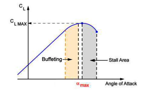
Figure 1. Lift of wing when the angle of attack varies. Source: Leeham Co.
Aircraft lift
Aircraft wings have a cross section called an airfoil. Airfoils for airliners are specially formed to fly at high Mach speeds. Before we go to these airfoils, we explore lift using a classical airfoil, designed for lower speeds.
I found a good description what happens with an airfoil when the angle of attack against the air is varied. The airfoil profile in Figure 2 is a NACA laminar wing profile and the graph is from the excellent book Race Car Aerodynamics by Joseph Katz. I’ve used the graph because he’s illustrative explanations are among the best.
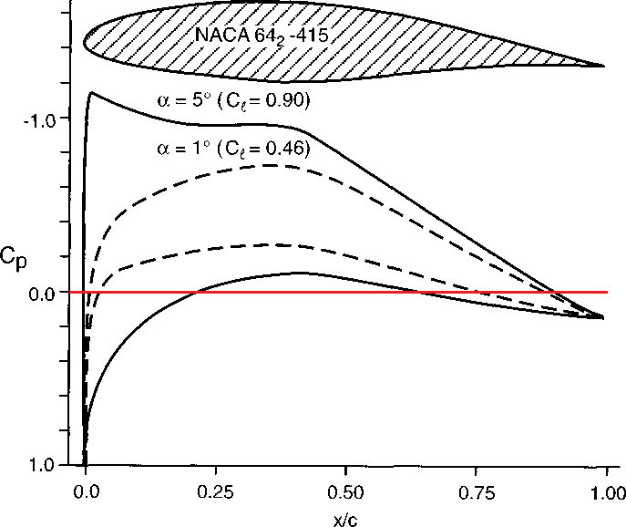
Figure 2. The effect of angle of attack on the lift and pressure distribution of a wing profile. Source: Katz, Race Car Aerodynamics.
When the air hits the front of the wing, the part of the air taking the top route curves around a convex shape, the wings nose. The speed of the air increases and the static pressure (Cp) decreases. At low angle of attack (1° in this case), the curving builds the top dotted pressure curve, passing into negative Cp. We have suction (negative pressure relative to surrounding air pressure) from 2% of the wing chord to around 90%.
For the air taking the route past the bottom of the wing, there is a slight suction created as the air speeds up when it curves around the convex section until 75% of the cord. Then the wing profile has a concave shape, which slows the air down and a positive pressure builds (the lower dotted line passes the zero line downwards).
If we increase the angle against the air (the 5° line), the suction has a peak early on the wing profile at a higher suction level. The pressure curve for the bottom of the profile has positive pressure at the beginning and end of the profile.
To calculate the profile’s lift, one sums the two curves, to a total lift called Cl. This is the lift per unit wing area. It has been made independent of the speed of the air and the air’s density.
As we can see the lift of the air is concentrated more to the front of the wing when alfa increases. A wing without a stabilizing tail would flip over backwards, even if the initial tendency to flip over could be controlled with a forward centre of gravity.
As alfa increases, the flipping moment increases and the forward CG doesn’t help anymore. This is what happened to one of Jack Northrop’s flying wings at a test flight after the war. The test pilot didn’t listen to warnings about the dangerous high alfa characteristics, pulled the flying wing into a high alfa situation, flipped over and crashed.
Flying wings have only become popular again (B2, B21, different UAVs) when Fly-By-Wire flight controls could make the Pilot avoid the dangerous high alfa regime of a flying wing.
Airfoil stall
As the angle of attack is increased further, the air can’t curve around the nose of the wing anymore. The boundary layer breaks away and the wing loses lift, it stalls (Figure 1). Before a wing passes into a stall, it’s starting to shake. Pilots talk about “wing buffet”.
This is a warning the airflow has problems to follow the wing’s top curvature, it breaks loose over areas of the wing. When designing a wing it’s important this separation of the flow starts at the inboard section of the wing so the outer section, equipped with ailerons, still has a functioning airflow. By it, the pilot can stop the aircraft from dipping its wings. Designers use wing twist to achieve a local lower angle of attack for the outer section of a wing.
In the next Corner, will look at a transonic wing’s pressure distribution.
What’s the graph reading from top to bottom?
Solid, 5 bottom of wing
Dot, 1 top of wing
Dot, 1 bottom of wing
Solid, 5 top of wing
?
From top to bottom:
Solid, 5 top of wing
Dot, 1 top of wing
Dot, 1 bottom of wing
Solid, 5 bottom of wing
Observe the scale is inverse. Top is lowest pressure, bottom highest. This is the standard way to draw pressure diagrams for wing profiles.
Thanks, that makes sense. In the 1 degree case, it looks like the maximum negative pressure is at about 38% of the wing chord. I assume this means these forces are acting against each other, upward suction on the top of the wing, and downward suction on the bottom of the wing. Seems like you should subtract the downward force from the upward force rather than add them?
Cp, is that pressure normal to the surface?
Exactly, it’s the integrated Cp difference, not sum. Pressure is always normal to the surface.
Going back to ‘aircraft drag reduction part 2’ in October, I’d be curious what the comparison of this pressure graph along the chord of a wing is for two cases described there. A flat plate at 20 degrees, and a cambered wing section at 20 degrees. I would guess that a flat plate sees no suction on top.
Looking at Fig. 2 above, for the 5 degree case, estimating area above and below the red line, it looks like the top of wing generates 5 to 10 times the amount of lift than the bottom of wing. This goes against my intuition, although that has always been the description of the main component of how lift works, the Bernoulli principle. Also interesting that the negative pressure from this effect (-1.2), can exceed the direct pressure of a surface normal to the slipstream of 1.0
The CL/CD is insteresting “The glid ratio”, which commercial airline has the best presently? One can assume that a light weight aircraft with a big wing can be optimized easier for the best Cl/Cd.
I bet the new ERJ190, A330-800, B787-9, A350-900, MRJ90, CS100, 737MAX7, A319neo, MC-21 and Sukhoi SSJ100 can be in the race.