Leeham News and Analysis
There's more to real news than a news release.

 Leeham News and Analysis
- Boeing defends 787, 777 against whistleblower charges April 17, 2024
- Dissecting Boeing CEO’s statement next new airplane will cost $50bn April 15, 2024
- Bjorn’s Corner: New engine development. Part 3. Propulsive efficiency April 12, 2024
- A350-1000 or 777-9? Part 2 April 11, 2024
- Pontifications: Boeing “transparency”–not so much. April 9, 2024
Bjorn’s Corner: Aircraft stability, Part 4

By Bjorn Fehrm
May 4, 2018, ©. Leeham News: In the last Corner, we discussed basic autopilots used in general aviation aircraft. The key components for such a system are shown in Figure 1.
Now we will go to more advanced autopilots. We will start with describing the sensors such autopilots need.
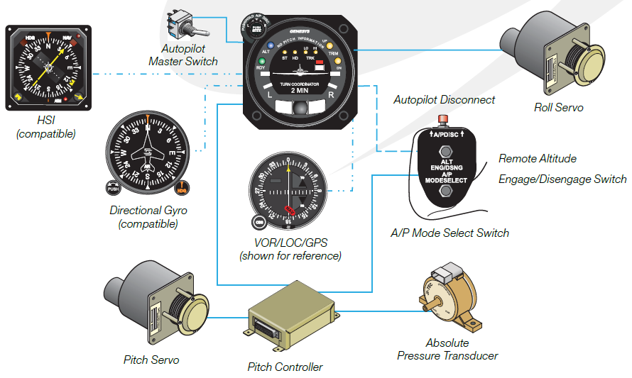
Figure 1. The S-TEC 30 roll and pitch two-axis autopilot. Source: Genesys.
Advanced autopilots
In the last Corner, we described autopilots based on turn indicator gyros and altimeter sensors. Through the clever processing of the signals, such autopilots can get quite sophisticated. They can:
- Control the aircraft in roll. Through roll steering and inputs from directional gyros and Navigation receivers, the more advanced autopilots can be programmed to intercept and capture an ILS localizer signal or follow a GPS navigator’s route including turns.
- Control the aircraft in pitch. Through inputs from Altimeter sensors and Navigation receivers, the more advanced autopilots can be programmed to climb or descend at a certain rate and to capture and hold a pre-programmed altitude. It can also capture an ILS glideslope signal and by it, fly a coupled ILS approach.
The more advanced variants include yaw dampers and add additional servos to manage the trim of the aircraft in roll, pitch and yaw.
Figure 2 describes the most advanced rate gyro-based autopilot sold by S-TEC, the System 65. It costs around $50,000 excluding installation. Click on the picture to read about the many capabilities.
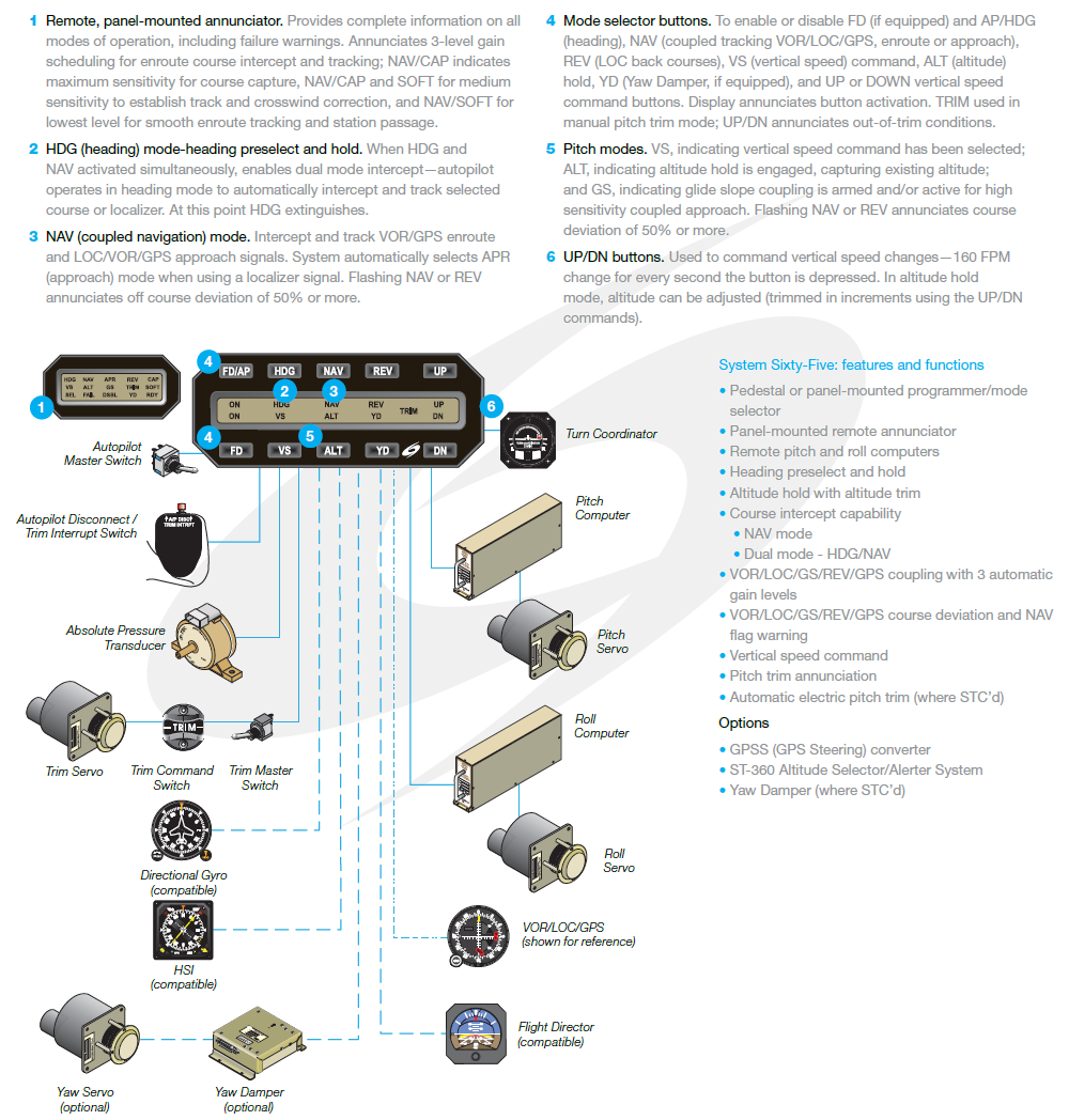
Figure 2. The most advanced S-TEC autopilot based on a Turn indicator sensor. Source: Genesys.
To go beyond the capabilities of these autopilots, we need a more sophisticated sensor than a rate gyro for roll and pressure transducer for pitch. Traditionally such signals were taken from the aircraft’s attitude gyro. These were mechanically spinning gyros until recent glass-based cockpits.
As such, they had limitations in roll and pitch and could tumble during violent pitch and roll manoeuvres such as when losing control of the aircraft (gyro tumble). They also got old and could start to drift in their stabilization because of bearing friction.
The first replacement for these mechanical spinning gyros were systems using solid-state lasers shooting rays in a ring and where interferometer sensors told the gyro’s electronics about the attitude changes.
Such gyros were built into 3 axis Attitude and Heading Reference Systems (AHARS) which form the heart of the aircraft’s sensor suite for the controlled flying of the aircraft. Laser gyros are expensive and are today used in high-end Navigation systems based on Inertial Navigation units providing the AHARS signals.
For most AHARS applications the mechanical gyro and the ring laser gyro has been replaced by the gyro types we find in game controllers and image stabilized cameras, MEMS gyros (MEMS stands for MicroelEctroMechanical System).
The MEMS gyro comes packaged like an electronic component and has miniature vibrating forks inside. These resist rotation and the resulting force is read by smart electronics which outputs the attitude signals.
MEMS-based gyros are now combined with micro accelerometers to reliable and capable AHARS units. Figure 3 shows the different systems in an aircraft which would use the signals from an AHARS.
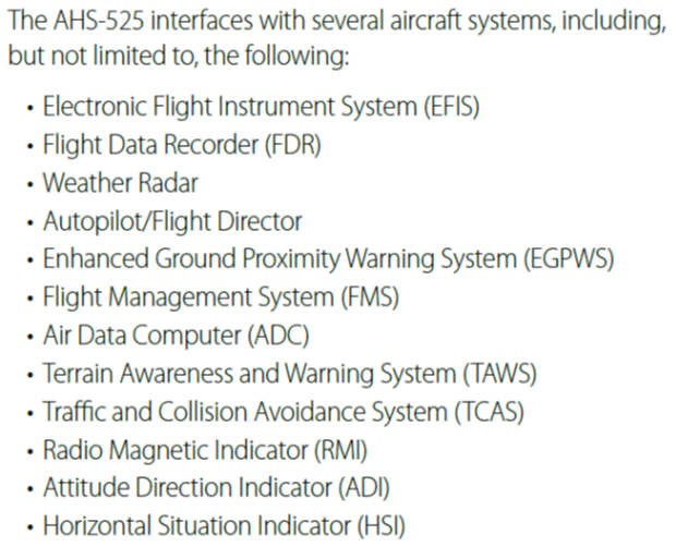
Figure 3. List of possible users of AHARS data in an aircraft. Source: Universal Avionics.
In next week’s Corner, we will describe autopilots which are built around these modern attitude sensors.
Off topic but a nice article on the 747, which must have seen many changes in the autopilot systems over its life span.
http://c.newsnow.co.uk/A/936425979?-303:3665:3
MEMS gyros are not very well suited advanced navigation capabilities (RNP AR and CATIII). For that, the laser ring gyros are still the best, and will not be replaced so soon. Also, MEMS gyros has coupling issues with flexible body dynamics. This requires additional filtering, which makes their closed-loop performance very limited. Maybe for general aviation it could be a cheap solution, but not for commercial airliners. I don’t know which is the direction the next corners will follow, but just like to leave my two cents.
“laser ring gyros”
mirrored or fiber ?
Thanks Max. Agree. The MEMS-based AHARS are used today up to midsized business jets, aided with GPS and other means to fix their drift and other problems. For larger biz jets we talk Fiber Optical Gyros (FOGs) which is a cheaper ring laser variant. For airliners and top biz jet’s we are at mirrored ring laser gyros and the AHARS is then a full inertial platform. To be discussed in the next corners.