Leeham News and Analysis
There's more to real news than a news release.

 Leeham News and Analysis
- Bjorn’s Corner: New engine development. Part 4. Propulsive efficiency April 19, 2024
- Boeing unlikely to meet FAA’s 90-day deadline for new safety program April 18, 2024
- Focus on quality not slowing innovation, says GKN April 18, 2024
- Boeing defends 787, 777 against whistleblower charges April 17, 2024
- Dissecting Boeing CEO’s statement next new airplane will cost $50bn April 15, 2024
Bjorn’s Corner: Aircraft stability, Part 6

By Bjorn Fehrm.
May 18, 2018, ©. Leeham News: In the last Corner we discussed the autopilots one finds in Turboprops and entry-level Business jets. Our example was the autopilot for the Garmin G1000 integrated flight deck.
Now we will step up to the airliner level. We will look at the autopilot and its supporting avionics for the Bombardier CSeries. This is a modern, state of the art system, and a good example of the autopilots for an Airliner or top of the line Business jet.
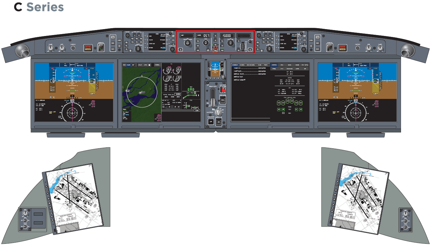
Figure 1. The CSeries flight deck. I have marked the autopilot panel with a red border. Source: Bombardier.
Autopilots for Airliners and Large Business jets
The autopilot for the CSeries is a good choice for a high-end system. It’s used in the newly introduced CSeries, an aircraft I could test-fly 18 months ago. But it’s also used in Bombardier’s high-end Business jets, the Global 5000, 6000 and 7000.
It means the description for the CSeries is also an example how a high-end Business jet like a Bombardier Global, a Gulfstream or Dassault Falcon would be equipped.
It will be a bit more complicated to describe the autopilots for this class of aircraft, as the functionality is not found in one system, but several. We will, therefore, cover the build-up of the system in this Corner and discuss the functionality and use of such a system in following Corners.
The Automatic Flight Control System for airliners
The system which is helping the pilots fly the daily airliner missions is called Automatic Flight Control System (AFCS). The different parts of an Automatic Flight Control System are shown in Figure 2.
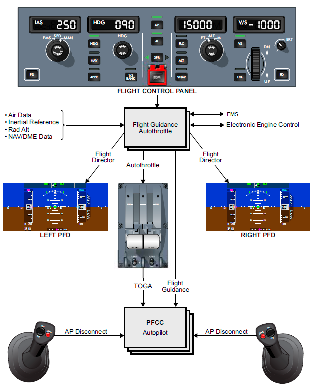
Figure 2. The Automatic Flight Control System of the CSeries. Source: Bombardier.
The Autopilot is now an application in the Primary Flight Control Computer (PFCC) of the Fly-By-Wire system (low box in Figure 2), executing commands to the flight control surfaces of the aircraft.
The key part of the system is the Flight Guidance and Autothrottle computer, calculating the commands to the Flight Director (FD) bars on the Pilot’s Primary Flight Display (PFD) and to the Autopilot and Electronic Engine Control. We will cover what happens in these boxes, but let’s start with the sensors such a capable system needs.
On the upper left, we have Air Data. This is a system which measures the aircraft’s speed and altitude. It also keeps track of the outside temperature. On an airliner, there are at least two complete Air Data systems with a third backup system serving the standby instruments.
Here we also have an Inertial Reference System (IRS) instead of an Attitude and Heading Reference System (AHRS) as described in previous Corners. This means the aircraft can cross for instance the Atlantic without the assistance of any Navigation aids, knowing its position and attitude by the force measurements made by the sensitive inertial ring laser gyros forming the heart of the IRS. The IRS is also doubled on an airliner, for redundancy.
In addition, the airliner has Radio Altimeters, measuring the distance to the ground when landing, and a multitude of Navigation and Communication radios.
The Automatic Flight Control System works with the aircraft’s Flight Management System, the FMS. The FMS stores the flight plan for the route with all navigation, altitude and speed information. It also contains an aircraft performance model so it can calculate the best flight profile for the mission.
The FMS will recommend when the aircraft can increase its Flight Level (altitude) when it burns off fuel and gets lighter. It also manages all the navigation systems and calculates steering commands to the flight Guidance system to keep the aircraft on the Flight Plan both laterally and vertically.
The hierarchy for the systems during a mission after take-off and until landing is:
- The FMS is the overall boss for the mission. It gives the Flight Guidance computer commands to keep the aircraft on the planned path laterally and vertically.
- The Flight Guidance Computer calculates what attitudes and thrust settings are needed to do as the FMS says. It changes the positions of the Flight Director’s bars on the PFD (bars on an airliner, Vs on a business jet) and gives thrust commands to the Autothrottle.
- The Pilot can decide if he wants to fly manually according to the Flight Director (matching the FD crosshairs and keeping the speed with the throttles) or engage the Autopilot and Autothrottle to do it for him.
When the Pilot decides to let the Autopilot and Autothrottle step in, he can still intervene and control the Flight Guidance through the Flight Control Panel at the top. He is then flying a mixed manual and FMS based flight. He can also reprogram the FMS and use the TOGA and AP Disconnect buttons in the Figure for further control during Take-Off and Landing.
In the next Corner, we will discuss these choices and the impressive abilities of an airliner Auto Flight Control System.
Hi Bjorn, the CSeries has Autoland for CATIII operations. Is it capable of performing CATIIIB? If so, who controls the Nose Wheel Steering for rollout, if the aircraft does not have servos?
According to the BBD sales literature CATIIIA is standard and CATIIIB is an optional feature. https://commercialaircraft.bombardier.com/content/dam/Websites/bca/literature/cseries/BCA_5472_01_Brochure_CSeries_F_WEB.pdf
At the time I flew the aircraft it was still working on the CAT3 certification (which was always planned to be done after EIS certification). It should be done by now. Control of the nose wheel is no problem, there is input under the control of the FBW, in fact, you can use both the pedals and a tiller for controlling the nose wheel. The mixing and limits on authority are under the control of the FBW.
Thats good that the control on the ground is part of the FBW, as it appears to me a lot of skidding off runways ‘after landing’ and sometimes even before takeoff happen with the 737
Hi Bjorn
Why does the advanced autopilot on the C-Series use laser ring gyros when Micro-Electro-Mechanical System (MEMS) gyros are available and are used on other aircraft, as described in an earlier post in this series?
MEMS gyros are the least accurate gyros. The Hierarchy in terms of performance (drift…) goes:
1. Mechanical gyros (still the best but have long-term reliability issues), used for inertial platforms.
2. Ring laser gyros (best of the non-mechanical but expensive), used for inertial platforms.
3. Fibre Optic Gyros (FOGs, cheaper than ring laser but not as good), used for high-end AHRS.
4. MEMS Gyros (cheapest, but not very stable), used for low-end AHRS.
RNP AR and CAT3 operations requires high precision IRUs with very small drift rates, that only Laser Ring gyros can provide. I heard that SAFRAN is working on a vibrating mass gyro that seems to have the same accuracy as laser ring, but the current ones provided by Honeywell and Thales are mostly Laser Rings.
“a third backup system serving the standby instruments.” Speaking of which, where are those standby instruments located? I haven’t been able to find them in Figure 1. Or are standby instruments no longer analog “gizmos” (for lack of a better term) ?
The Integral Standby unit is just below the autopilot panel in Figure 1, between the Multifunction Displays. It’s a self-contained unit with AD (Air Data unit), AHRS (Attitude Heading Reference System) and display.
I remember discussing that previously, spotted it right off.
Most interesting. How visible and realistically usable is it?
The modern standby units are good. They are used as primary instruments for small aircraft like gliders and modern single-engine general aviation aircraft where there is a space problem. Check this out:
http://www.l3aviationproducts.com/products/esi-500/
http://www.l3aviationproducts.com/products/trilogy-esi/
So it too is digital. I guess I was looking for good, old fashioned analog gauges.
Its a digital cockpit. They would have had to add a conversion to make it synthetic analogue unless you were looking for ‘analogue style’