Leeham News and Analysis
There's more to real news than a news release.

 Leeham News and Analysis
- Dissecting Boeing CEO’s statement next new airplane will cost $50bn April 15, 2024
- Bjorn’s Corner: New engine development. Part 3. Propulsive efficiency April 12, 2024
- A350-1000 or 777-9? Part 2 April 11, 2024
- Pontifications: Boeing “transparency”–not so much. April 9, 2024
- Airbus charges and write-offs since 1999: more than €33bn April 8, 2024
Bjorn’s Corner: Fly by steel or electrical wire, Part 9

By Bjorn Fehrm
September 20, 2019, ©. Leeham News: In our series about classical flight controls (“fly by steel wire”) and Fly-By-Wire (FBW or “fly by electrical wire”) we discussed the FBW flight control system of Embraer’s E-Jet E2 series last week.
We have now covered examples of classical flight controls and their modern FBW counterparts. Now we discuss how these handle different stability augmentation needs like Yaw damping, Mach tuck protection or Pitch control improvements like the Boeing 737 MAX MCAS system.
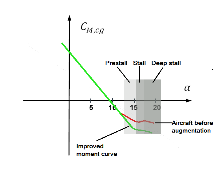
Figure 1. The pitch moment curve of a modern airliner. Source: Leeham Co.
The need for stability augmentation
We have described how airliners which cover a large speed and altitude envelope need assistance from a flight control system to provide adequate stability in all corners of the flight envelope in our Stability Corner series.
To avoid the uncomfortable yaw/roll phenomenon Dutch Roll all airliners implement a Yaw damper using the rudder to stop the airliner from wagging its tail while flying.
Further, at high speed, the aerodynamic center moves back due to transonic effects on the wing and we need Mach tuck protection. It’s implemented as an automatic nose up trim using the movable horizontal tail.
T-tail aircraft has a problem where the wing shadows the high placed horizontal tailplane at high Angles of Attack (AoA). Therefore, T-tail airliners/business jets implement a stall avoidance system called a Stick pusher, pushing the nose of the aircraft down if the pilot ignores stall warning and increases the AoA into the stall region.
Key to the Yaw damper and Mach tuck protection implementations for flight control systems are their control authority. For a Yaw damper, it’s typically 5% of the deflection authority of the aircraft’s rudder. It’s enough to stop the tail wagging which triggers Dutch Roll and is limited enough to not endanger the aircraft if there is a “hard-over” fault causing the damper to deflect fully in one direction. This simplifies the requirements on the damper system and also on the infra-structure supplying the damper with electricity and hydraulics.
The same goes for a Mach tuck trim system. Its trim authority is limited so if it has a failure it can’t endanger the aircraft. The pilots can use the elevator followed by manual trim to neutralize a wrongly executed Mach tuck trim.
The Stick pusher is more tricky. By design, a stick pusher creates a distinct nose-down movement of the control Yoke to avoid entering stall Angle of Attack. The pusher must be precluded from endangering the aircraft if it activates erroneously. This can be achieved by making the servo so weak the pilots can overpower it by pulling on the Yokes or by deactivation the pusher in certain configurations like at take-off or in the landing phase when full flaps are activated with an extended gear.
For a Pitch argumentation system like the 737 MAX MCAS it gets trickier still. The system is there to make the aircraft consistent in pitch control all the way until stall. Modern airliners often have a region of reduced pitch stability before stall, Figure 1. It’s caused by the aerodynamic center of the wings moving forward caused by today’s larger engine nacelles disturbing the flow over the wings at high AoA.
Depending on the needed augmentation at different parts of the flight envelope this system needs more or less authority. For a classical flight control system, this is more challenging to implement than for a FBW system. We will discuss why in the next Corner.
Bjorn if MCAS 1.0 was intended to improve the pitch moment curve, to produce the green line on your Figure 1. above, why did BA not use the Elevator Feel Shift Module.
If they were intending to make the MAX ‘feel’ like an NG, I don’t understand why they didn’t use an existing system (EFS) to alter the force required to pull back on the control column when approaching a stall.
It seems that even on the NG EFS is used to increase forward control column force to approximately four times normal feel pressure during a stall.
I can’t see why you would add an extra system when you already have one that is pretty much a perfect fit for the job.
The Elevator Feel Shift changes the neutral point of the elevator, by it changing the middle point of its travel and stealing authority from the pilot. You could say the elevator is the pitch tool for the Pilot and the HTP trim the tool for the aircraft augmentation systems when it comes to pitch helper systems. Of course, the Pilot also uses the HTP trim. It’s for neutralizing Yoke forces in pitch but also to safeguard the elevator is always available for full authority pitch corrections by him.
Thank you for the reply Bjorn, I will digest that.
I still can’t really understand why the stabilizer was used to modify the ‘feel’ of the aircraft, especially as it moved in ‘steps’ in the MCAS 1.0 incarnation.
I find it odd that ‘steps’ are used to smooth a curve. I would have thought the stabilizer movement in that case would mirror the increase in angle of attack, in direct proportion.
Is it the case that as the stabilizer is slow moving relatively, it would not keep pace with the increasing angle of attack ?
In the EASA publication re MCAS the feature is deemed an “anti stall device”. the Tzar is naked.
Afaics people at Boeing seem to have decided that a bit of touchy feely aid is not enough to counter an imminent entry to stall.
I suspect we haven’t learned everything yet from the MCAS disaster and why it was added. Apart from the additional pitching up moment generated by the big further forward LEAP 1B engines perhaps there is a kind of super-stall effect from the big engines interfering with airflow over the elevator. I think it’s probably simple: the bigger LEAP engines on the MAX generated a pitch up force at around pre stall that was more than the CFM56 on the NG and this extra pitch up was neutralised by MCAS trimming the elevator down. This also maintains both elevator authority and elevator feel. You pose an interesting question regarding why MCAS didn’t continuously proportion elevator trim in as alpha increased and the remove it as alpha reduced. I suspect it’s because Boeing hardly ever thought MCAS would activate and that it wouldn’t operate for its full 9 seconds and that manually un trimming was best since some kind of emergency condition had created the need for trimming down the elevator.
William, the MCAS system was added to the Speed Trim System (STS) of the current stabilizer control on the 737. It’s not been described that well anywhere I’ve seen online. Here’s a link briefly describing the older 737 primary flight control systems.
===========
http://www.dutchops.com/Portfolio_Marcel/Articles/Flight%20Controls/B737_Flight_Controls/B737_Primary_Flight_Controls.html
==============
The stabilizer is much more powerful but, slower in response than the elevator. With MCAS, they at the last minute in the testing phase changed the speed of MCAS after a test pilot said they needed a quicker response to the pitch up issue. The STS only was tied into one AOA vane. It was never designed originally to be flight critical. The elevator on the 737 seems to be too weak to overpower the stabilizer on the 737. It’s quicker in response. Boeing seems to be trying to make the stabilizer into a stabilator. (one big combination stabilizer and elevator). MCAS moved the bigger, slower responding stabilizer because it tied into the speed trim system, which already moved the stabilizer. It seemed the easiest way to go at the time with all of the restraints put on the design team. A good engineering review was either ignored or not properly done. The accident flights didn’t have the option of only turning off MCAS. Boeing took that away when they rewired the stab cutout switches. They only had the option of turning off the electric stabilizer motor leaving them with a slow, manual cable system, which seems to have been too weak to work the system at the speed and settings they had. The elevator couldn’t overpower the stabilizer. How to fix the system properly now is the problem Boeing is left with. They seem to be opting for a software change only at this point.
Or when the wing enters the prestall region at relatively high AOA the nacelle interferes with the airflow over the wing right behind it creating sudden flow separation over the wing resulting in loss of lift.
At that time the nacelle it self has not started to stall, still creating full lift resulting in suddenly shifting the centre of lift forward.
Thanks Richard Davenport and Hildebrand. There is probably a lot going on aerodynamically in the LEAP 1B installation, the wing behind the engines and the stabiliser and elevator. Once EASA determine the aerodynamic behaviour of the B737 MAX they will know how critical continuous MCAS availability is to safe flight and be able to determine what level of fault tolerance and redundancy is required. Hopefully a 3rd alpha sensor and a backup electric trim motor isn’t required. I suspect an all flying tail or stabilator similar to the L1011 Tristar would also have worked but again the existing hydraulic systems probably would have been inadaquete to support such a tail and it wouldn’t have supported the existing type rating.
Interestingly the Hawker Siddley Trident and BAC 1-11 both had an irrecoverable super stall problem in which the wing in a stall could blank of air flow to the stabiliser as well as stall the engines. To overcome this auto light was added to the engines and a powerful compressed air system was used to operate a stick pusher to over power the pilots and put the nose down. The system could be deactivated in flight but to prevent a false triggering thebBritish CAA required redundant sensors and fail safe design. It’s a pity that Boeing didn’t learn from this. Apparently B727 didn’t have a stick pusher, you just made sure it never stalled. The VC10 could recover from a stall due to the high sweep and wing tip dog tooth leading edges providing enough forward pitch. The highly swept tail and winglet effect of the 4 engines also helped. CAA had a stick pusher installed anyway. Same with IL-62. There is a kind of precedent for this problem in T tail aircraft.
MACS wasn’t just a full step implementation. But the AoA reading it acted on in the 2 crashes was sufficIent to get the full movement.
That’s constantly overlooked. So is the resetting the pilots did with manual electric trim. Or even how MACS was designed to remove the added trim when the high AoA situation was resolved.
Am I correct in that the 737 NG has an Elevator Feel system to increase the yoke force about 4X, when close to a stall, and that the 737 MAX has the same Elevator Feel system, along with the additional MCAS system? In reviewing a previous Leeham News article
================
https://leehamnews.com/2018/11/28/indonesian-authorities-release-preliminary-lion-air-crash-report/
============
on the Lion Air maintenance before the accident flight, a lot of messages mentioning the new Stall Management Yaw Damper (SMYD) system, and the Air Data computer were being noticed and corrected. They then replaced the AOA vane itself as it was also showing up in the messages. So, the next flight, that shut down the trim motor before MCAS activated too many times had to fly with the 4X yoke forces, and the stick shaker going off was flying with a shiny new AOA vane. There seems to be more at work here, than just a faulty AOA vane, unless there was a bad batch of AOA vanes or a problem with the installation, calibration and testing of the newly installed AOA vane? Everyone is focused on MCAS and the AOA vane. There’s a lot of new FBW SMYD technology in the computer system that was issuing warning messages before the crash also. I hope some of this is resolved or detailed in the soon to be released KNKT final accident report.
Re AOA vane- unit
Two or more possible issues
1) Ramp rash due tohigher nose wheel – forward loading dock
2)Close exam of AOA sensor manufacturing shows a sensor attached to the vane by a setscrew to hold- adjust sensor in alignment with vane. IF screw loose- then sensor unit can rotate relative to vane..
Seems to me a p poor method used for kiddies toys instead of a spline or d shaped shaft sensor assembly.
Granted hundreds have been in use for years, but there have been a few problems that **may** have been related
3) Bird strike on AOA vane- coupled with insane one sensor only control of major flight surface.
4) Unusable trim wheel also affects NG and even if lower speed, nearly impossible to turn enough times in time available at low altitude.
5) Possibility that IF crews had been warned of process to electrical trim to near normal, immediately switch off and then trim wheel could be used for fine ‘ trim ‘
Of course in the world of IF …..my aunt had ….., she would have been uncle- she didn’t and wasn’t
If this is correct, it appears that MCAS can be switched off !
https://www.flightglobal.com/news/articles/silkair-cleared-to-move-737-max-fleet-to-alice-sprin-461021/
“The flight will also be operating without its manoeuvring characteristics augmentation system (MCAS), the software that has been implicated in two fatal 737 Max crashes.”
I wonder how this is achieved, I would have thought that as MCAS is part of the software, BA would have to have a version of the software that had MCAS disabled in order to ‘switch off’ MCAS.
That would imply that they had to flight certify both versions of the software wouldn’t it ?
@Bjorn I do wonder how the ‘feel’ of a FBW aircraft such as the A320 is modified between say the A318, and the A321. Does AB use the stabilizer to modify the pitch feel ?
JakDak, If flaps are deployed, or the AP is on, then MCAS is not activated. For these flights, CASA has ordered them to fly using flaps all the way.
https://mainlymiles.com/2019/09/12/silkair-to-fly-its-grounded-737-max-aircraft-to-australia-for-storage/comment-page-1/
So far as I know, there is no “OFF” switch for MCAS, other than what is built into the software for flaps and AutoPilot, or in the future, bubble gumming the AOA vanes to be over 5.5 degrees out of kilter.
Ouch that’s got to be a tedious, and expensive flight. Flaps extended, and not exceeding 20,000 feet.
What would be the max speed they could fly with flaps 1 ?
I’m guessing the flight from SIN to ASP would be considerably longer than five hours ?
JakDak, I’m not a 737 pilot, but. looking around the internet, it appears like the maximum speed for flap extension is 250 kts, but, typically 200 kts for a flaps 1 setting. A nice scenic flight. The max flap altitude looks to be 20000 ft also. But, as I said, I”m no expert. I’ve never been in a 737 cockpit, at altitude.
I think this article has been around for a while, if this is true it paints an even worse picture of the MAX, and the regulators, EASA included.
https://uk.reuters.com/article/ethiopia-airplane-regulator/corrected-insight-regulators-knew-before-crashes-that-737-max-trim-control-was-confusing-in-some-conditions-document-idUKL3N21G2D8
“It specifically noted that at speeds greater than 230 knots (265mph, 425kph) with flaps retracted, pilots might have to use the wheel in the cockpit’s centre console rather than an electric thumb switch on the control yoke.”
But as we have now found out, using the manual trim may also not be an option.
I think they’re missing something “the relative rarity of conditions requiring the trim wheel” it only has to happen once in the wrong circumstances for people to die !
I had thought that if they returned the MAX trim cut-out switches to the NG style, cut-off for autopilot/MCAS, and full cut-out, they wouldn’t need to address the manual trim issue, but if the electric trim isn’t any use above 230 knots, they need to fix manual trim !
Article misstates the issue.
Electric trim can’t go past a limit switch, So to go further, to the mechanical stops, you have to use the wheel.
But that’s further in the direction of the limit hit.
Trimming AND electrically stops before the mechanical limit. To get full AND you use the wheel. Even when past that limit you can trim ANU electrically.
The inverse is also true. ANU limit can be passed with wheel and still return AND electrically.