Leeham News and Analysis
There's more to real news than a news release.

 Leeham News and Analysis
- Solid start for stand-alone GE Aerospace despite cuts to LEAP output April 23, 2024
- SPEEA, Boeing at impasse over safety program, union says April 23, 2024
- Better transparency needed on Boeing’s 1Q earnings call April 22, 2024
- Bjorn’s Corner: New engine development. Part 4. Propulsive efficiency April 19, 2024
- Boeing unlikely to meet FAA’s 90-day deadline for new safety program April 18, 2024
Bjorn’s Corner: Why e in ePlane shall stand for environment, Part 9. Hydrogen, cont.
February 14, 2020, ©. Leeham News: Last week we started looking at hydrogen as an alternative energy source for our air transport system. We discussed the use of hydrogen as a direct fuel replacement to jet fuel, burning the hydrogen in the combustor of the aircraft’s turbofans.
Hydrogen works fine as a fuel for the turbofan but it has challenges in its onboard storage, it’s handling and production. Good reader discussions followed around those problems. Now we look at hydrogen as a fuel in a fuel cell/electrical motor propulsion system.
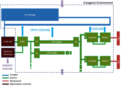
Figure 1. Components of a fuel cell-based aircraft propulsion system. Source: NASA.
Hydrogen as a fuel for a fuel-cell based electrical propulsion system
Figure 1 shows the components in a fuel-cell based airliner propulsion system with hydrogen as the energy source. The system has the same hydrogen fuel with the same benefits in energy specific weight and the same problems of storage, handling, and production as discussed in last week’s Corner.
Instead of burning the hydrogen in a turbofan combustor we now combine it with oxygen from the air to produce water and electrical current in a fuel cell. The fuel cell, in turn, drives fans propelled by electrical motors. We also need inverters and an electrical distribution system to complete the system.
The fuel cell in itself can be designed for efficiency of around 60%. The problem is the fuel cell’s volumetric power density and weight. The system then adds the weight and losses of the electrical propulsion system when compared to a hydrogen or jet fuel driven turbofan system.
There are good modeling studies done on the volume and weight consequences of such a system. In summary, the fuel-cell based propulsion system weighs about twice as much as today’s jet fuel based turbofan propulsion system.
The weight and volume requirements of the system will gradually improve over time and at least we are not 70 times off as for a battery-based power source. For now, a turbofan based hydrogen system holds more promise than a fuel cell one.
There are a number of fuel-cell based experimental aircraft projects, all of them for small aircraft. But contrary to what one thinks, the fuel cell system works better the longer range the aircraft shall have. This comes from how the weight of the hydrogen storage part scales compared with the weight of the other system components dependent on the required energy stored in the system.
An interesting development for this system type is the CHEETA study NASA issued to a team of US institutions and universities last year. The CHEETA concept uses the low-temperature requirements of liquid hydrogen to cool the electrical power chain to superconducting levels to minimize the end to end losses of the system.
How far this can be designed as a practical system remains to be seen, but it’s at least an interesting idea as the practical storage method for hydrogen for longer range operation is its low-temperature(-253° C) liquid state.
In next week’s Corner, we start putting our discussions into the larger environmental context.
If the hydrogen can be used for cryogenics without significant evaporative loss of fuel, then the weight of the fan components might be on par with turbofans. Experimental cryogenic motors have been built with turbofan specific power, but not simultaneously at the same scale.
The weight of the fuel cell and inverters would still be extra for that case. It would seem that scaling up to multi-megawatt capacity would be a critical factor for both motors and fuel cells.
If the fuel mass is lower for hydrogen, then some of that gain would offset the additional weight for fuel cells and components. But as noted in last week’s Corner, the landing weight still would be higher than conventional fuel. So it all depends on the scaling that can be achieved.
The CHEETA project at UIUC is really interesting, even the design of the aircraft itself.
Things are moving at an increase speed on the Fuel Cell industry
The cost of producing H2 from renewable sources has fallen by 60% the last 10 years and it is on track to do the same in the next 10. (1)
Something similar can be said about the Fuel Cells’ total cost of ownership. (2)
I hope that this will increase the options of the “FCAV”
(1) https://www.h2-view.com/story/new-report-from-the-hydrogen-council-says-the-cost-of-hydrogen-will-fall-sharply/
(2) https://blog.ballard.com/fuel-cell-price-drop
Weight is still the problem …not cost.
More Weight is a serious setback , due to increased drag due to lift. In addition the efficiency of the fuel cell is 60% compared to 95% directly from batteries.
Once again kerosene turbofans are way ahead….not that hydrogen devotees will see reason.
But compared with batteries, the head start in weight is already huge and it gets better with range.
It is clear that the kerosene turbofan is more efficient; but the point is to not emit CO2 and NOx, isn’t it?
It’s all a matter of the trade off between the propulsion systems efficiency versus the cost of the extra weight at a certain point the improved efficiency will pay for itself in reduced fuel weight. NASA’s Glenn Research Centre has achieved very good power densities in its fuel cell research. The result is a BSC SOFC (Solid Oxide Fuel Cell) that can achieve high specific power densities that are five times higher than state-of-the-art (up to 2.5kW/kg), and a volumetric power density that is eight times higher than state-of-the-art (up to 7.5kW/L).
For Comparison a Ww2 Single Stage Merlin could achieve about 1.8kW/kg (not counting the cooling system). The Siemens SPD260D electric motor produces 261kW out of 50kG so about 5.2kw/kg hence a fuel cell electric combo should be about 20% lighter than a WW2 piston engine aircraft not counting the savings from the lack of vibration. My back of envelop calculation suggest that at 70% cruise power the fuel cell which is twice as efficient as the Merlin and 50% more than the latest gas turbine should pay for its extra weight in about 3 hours or so over a turbine which is about 1/3rd the weight. Other effects are that the turbine aircraft gets lighter towards landing again as its fuel empties and that the bulky cryotanks of the fuel cell aircraft are smaller than they otherwise would be.
My personal expectation is the continuation of use of hydrocarbon jet fuel however a synthetic Carbon neutral form derived from PtL. These catalytically made jet fuels have nice consistent liner chains that burn smoothly and without soot which come from non linear molecules in fossil fuels. It takes so much energy to liquify hydrogen that making a synthetic is competitive., potentially 60%
If the Fuel Cell makers keep improving at the current pace, it won’t take long to get to power densities that meet the criteria for aviation. However, one would assume they are picking off the low hanging fruit now and that things will get harder as density goes up. In the FCEV I’m driving the carmaker (kind of) took it one step too far for current tech. But there’s a fair amount of well respected scientists who believe that it’s possible to drive the weight of Fuel Cells down to where it becomes much more viable for aviation. Unlike batteries, where even Tesla’s top battery guru is on YouTube criticizing the Eviation project for battery weight. (Project isn’t mentioned by name, but it’s kind of obvious which project he’s referring to.)
Longer range makes sense. If you have heavier propulsion system(fuel cell) but lighter fuel (as stated higher energy/kg of hydrogen ), the the more fuel(longer range) offsets weight penalty more.
Hydrogen (or ammonia) can be used to intercool the compressor on a gas turbine (making it less energy demanding to compress and therefore increasing the excess power from the turbine) and can also be used to recuperate the gas turbine (using heat exchangers in the exhaust after the turbine stage to raise the temperature of the compressed air as it goes into the combustor, reducing the amount of fuel that needs to be burned in the combustor to do that job). Kerosene is not so good for these purposes as it degrades and gums up fuel metering equipment. In most of today’s engines it’s just used to cool the oil.
The heat thus removed from the gas turbine can be used to improve the efficiency of a fuel cell, which does not need to be so big because it has the aforementioned gas turbine to help it provide power, and to draw off the waste gases and burn them. The heat can also be used to catalytically split ammonia into hydrogen and nitrogen.
I imagine such a hybrid arrangement being powered by both turbine and fuel cell at take off, and the turbine being drawn back to idle for cruise & descent.
I like your idea of having LH2 use as a coolant/heat exchanger of a turbofan before it moves as a gas to its fuel cell. I Think a good start would be to replace the APU and have it also running at altitude driving a tail fan accelerating the boundary layer. The water the fuel cell produces could be used in the Aircraft and also used to enhance the turbofan mass flow at selected operating conditions. Stationary powerplants often have water injection “wet” into the burner housing to lower compressor exit temp and increase Power thru increased massflow thru the turbines. Even the old JT9D-7AW had water injection at T-O.
“I like your idea of having LH2 use as a coolant/heat exchanger of a turbofan before it moves as a gas to its fuel cell.”
In a way an element in Reaction Engines concept for SABRE.
The Sabre engine is extremely complicated with its counter rotating turbine/compressor and its Helium and Hydrogen circuits with heat driven turbopumps besides the highly visible heat exchanger. Parts of the Sabre system can be used to enhance current day turbofans but the whole SABRE system needs fundung and testing of another scale compared to a “normal” turbofan to go from proof of concept to a safe, reliable and cost effective solution competing with SpaceX.
I hope they get the funding and can attract the most brilliant engineers of Europe to solve all the engineering challanges, it is the 21th century “Napier Nomad” rocket engine design.
If you want to ‘accelerate the boundary layer’ at the extremity of the tail , it’s easier to duct compressor air, but only makes sense at landing speeds.
Boeing who came up with a practical solution decided on a laminar flow over part of vertical tail surface.. look it up . Any guesses they would do that and ignore your ‘tail fan accelerating boundary layers’ or whatever you call it
The Boeing 787-9 tailfil static boundary layer HLFC does not give much benefit, I do know that the 717 relative large engines help accelerating part of the boundary layer for a better than expected performace gain. NASA and others calculate a significat benefit for a tail fan. The Single-aisle Turboelectric AiRCraft with an Aft Boundary-Layer (STARC-ABL) propulsor is just one of tem.
You mean this
“Sizing Power Components of an Electrically Driven Tail
Cone Thruster and a Range Extender ”
https://ntrs.nasa.gov/archive/nasa/casi.ntrs.nasa.gov/20160007561.pdf
“The STARC-ABL turboelectric single aisle concept
is a tube and wing style aircraft with two turbofans and
an electrically powered aft thruster. The configuration
has a 7 to 12 percent fuel burn benefit compared to a two
turbofan version using the same technology
assumptions (5)
. The power system transfers electric power
from wing mounted turbofans to an aft mounted thruster
fan. The motor for the thruster fan runs at a continuous
power rating of 3500 hp (2.61 MW).
The savings seem to be based on theoretical concepts rather than actual tests. I would say that a possibility so far
It seems the correct term is Sceptor used by others
It would be better to “precool” the air prior to any compression rather than “intercool” between stages. The Reaction Engines SABRE engine precools the air before any compression using hydrogen to slightly above the pinch point thereby increasing air density by 4.5 and reducing the turbo machinery size by a scale of 4.5:1. One reason we use intercooling is because we don’t have a cryogenic liquid to cool the air below ambient. Hydrogen and its tremendous latent heat of vaporisation allows the small amount of LOH to precool this recovering some of the energy invested in liquifying hydrogen.
The Motivation behind SABRE was to create an air breathing rocket that once at Mach 5.5 could convert to using an onboard oxidiser to achieve a SSTO single stage to orbit. It is now being touted as a solution to hypersonic or suborbital flight. (The ultimate solution to drag elimination)
The heat exchanger technology of SABRE can be applied to more conventional gas turbines. Some solutions to ensuring that ice from water or CO2 does not form have been solved.
Nevertheless intercooling to 0 Celsius before the IP stage would also provide much benefit.
I do not like the idea of ‘ammonia’ as a fuel. It is highly toxic. It is being routed as a solution for shipping. Toxic as in one breath can knock you unconscious. It is handled in an industrial scale in highly specialised refrigeration and industrial processes but it does not belong on an aircraft or car.
IMU the (passive) air scoop of the sabre engine should already provide for significant compression.
https://en.wikipedia.org/wiki/SABRE_%28rocket_engine%29#Inlet
with a temprise from 280K to 1300K Id expect a pressure ration around 60 ? ( is my number foo correct ? )
People think the Reaction Engines SABRE is odd and untried but that’s not quite true. What Allan Bond did is use a closed cycle brayton cycle gas turbine with a helium working fluid. The heat source is a heat exchanger with burner(for startup and exo atmospheric flight on LOX) or alternatively the heat from the precooler (for hypersonic endoatmospheric flight). The heat rejection heat exchanger uses the Liquid Hydrogen. The output shaft of brayton cycle drives a compressor that feeds the rocket chamber with the precooled compressed air or oxygen. A portion of this air is bled of to to operate the burner if the hypersonic intake heat is not enough.
Closed brayton cycle engines are every as light and more fuel efficient than the standard open brayton cycles we call gas turbines. They have much better part load performance and pollution control is vastly superior since the burner has far less constraints on it in terms of flame stability. The cost of the material and fabrication of heat exchangers has made these less attractive till now but there have been tremendous advances in micro tube heat exchangers. We also may see a secondary supercritical CO2 combined cycle on aviation gas turbines, these are 1/7th the size of a steam cycle.
1) We should consider reliability. What happens if the cryogenic system fails over water, for instance?
2) With hydrogen as fuel, what is the engine operating temperature, and would that require new materials in the hot section and turbine?
3) Hydrogen is not a fuel, so forgive me for using that expression. Hydrogen is an energy storage system for conveying sustainably-generated energy from wherever it was generated to wherever it is used.
What are you referring to in terms of cryogenic system failing over water? If it’s just a cryogenic tank, it’s just a tank with insulation. Just like a kerosene tank, but with more insulation. If you are talking about using the cryogenic hydrogen as a heat sink for achieving Super Conducting for Fuel Cell Electric flight it’s a different deal. But that too would be a passive system, so a ‘failure’ would likely be a full on leak, which would be just as catastrophic in a standard kerosene tank.
If the cryogenic system fails the system should still remain cold enough function for some time and even after loss of superconductivity the conductors will still work at reduced power. There are two ways to cool: refrigeration modules, commercially available, compact and reliable or a cryogenic liquid. In this case if liquid hydrogen is used as fuel we also have our cryogenic liquid. Run out of LOH and it’s a moot point that we’ve run out of cryogenic coolant. Not much coolant is needed. The conductors themselves don’t generate heat. We are only counteracting the ambient heat getting through the insulation.
If the cryogenics fail and the superconducting threshold is crossed, there is an inductive spike from the sudden & massive current drop, which causes a destructive magnetic quench event. To prevent this, most superconducting systems have sensors that will shut down well before that transition.
So this would be a loss or propulsion event for aviation, equivalent to total engine failure. There would likely need to be some redundancy in the cryogenics to deal with this in flight.
A restart would be possible if the motor temperature can be lowered below the superconducting threshold again.
I have no professional idea if it is practical to implement a “limp” mode for the superconducting motor or cable. It is possible to do so as superconductors are usually a composite structure of conventional and superconducting materials but I do not know how practical it will be. Current would be less than half of the rated current and we now have voltage drop and insulation limits to deal with. Perhaps if 10% of nominal power could be delivered by software changes in the inventors it would be a useful safety function that will keep an aircraft flying longer.
William, the resistance ratio across the superconducting threshold, for superconducting filaments embedded in a copper matrix, is typically 100 to 150. So the motor might be more like 1% power or less, after quench.
At that rate it would be better to stop and let the motor cool, then restart in superconducting mode ASAP. The copper allows for efficient cooling and also conducts some of the current during quench, easing the effect.
Redundant filaments or windings are one way to increase reliability. The best way may be to use a significant temperature buffer, say 40 K for a 70 K superconductor. LH2 should do that easily.
Another interesting feature is that superconducting motors require high current but low voltage, so hydrogen fuel cells are ideal in that the cell voltage is less than 1 volt.
Thanks Rob, very good information. You’re an electrical engineer? The “Blue Sky” for this is that Solid Oxide Fuel Cells that are turbo compounded will achieve 80-85% efficiencies, electric motors 100%, inverters 99% and that the electrolysis of water to hydrogen followed by liquefaction will be 80% efficient. Last time a checked it was 57%. This compounds to nearly 70% efficiency. The efficiency will alleviate the penalty of bulky LH tanks. It will also help solve the problem of where all the energy for water splitting will come from. My own view is that PtL Power to Liquids (synthetic hydrocarbons) should be persuaded now as this will eventually achieve 65% conversion efficiencies and will be amendable to conversion to pure LH production.
One of the main challenges to increasing power density in Fuel Cells is cooling. As the various Fuel Cell Electric Aviation projects develops and they get to the point where they start to optimize the Fuel Cells for Aviation, it will be interesting to see if they can utilize all that nice cool air that’s up there to improve power density.