Leeham News and Analysis
There's more to real news than a news release.

 Leeham News and Analysis
- Solid start for stand-alone GE Aerospace despite cuts to LEAP output April 23, 2024
- SPEEA, Boeing at impasse over safety program, union says April 23, 2024
- Better transparency needed on Boeing’s 1Q earnings call April 22, 2024
- Bjorn’s Corner: New engine development. Part 4. Propulsive efficiency April 19, 2024
- Boeing unlikely to meet FAA’s 90-day deadline for new safety program April 18, 2024
Bjorn’s Corner: The challenges of airliner development. Part 22. Flight tests

By Bjorn Fehrm, Henry Tam, and Andrew Telesca.
September 24, 2021, ©. Leeham News: Last week, we looked at the necessary Production Certificate for the production of our airplanes.
Now our program plan has approached the mid-phase of the Post-Launch phase. We start assembling our test aircraft to get to flight tests.
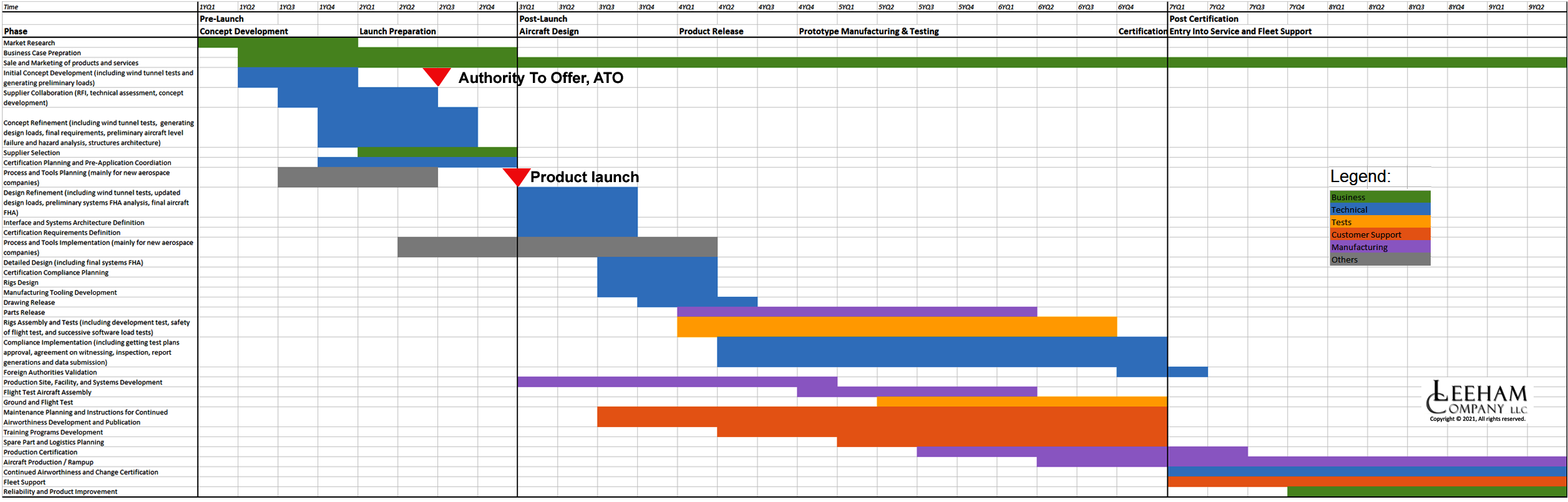
Figure 1. The program plan for our project. Source: Leeham Co. Click to see better.
Flight tests Aircraft production
We plan on using two Flight Test Articles, FTAs (OEM speak for test aircraft). We will also produce two ground test airframes, one for the static test to clear our flight test clearance (Limit load and Ultimate load tests) and another one for the cyclic tests to clear our fatigue envelope.
So in total four airframes are produced, whereof the second and third are stuffed with systems to make them flight test aircraft.
In general, we need to order the long lead-time items a year before we need them but these are the first pre-production items where all involved will learn how to produce the parts. We shall, therefore, add at least 50% lead times for the production of the parts, if not more.
Experience from the industry shows you need to spend about three to four times the manhours on the early items if these are new designs. For system parts that are derivatives of something that already flies, we can put the rule at double the time for the early production runs.
So we need ample pre-planning and margins for both calendar time and resources consumed, both at our suppliers and for ourselves at the assembly of the FTAs.
Why do early examples take such extra time? Because after each produced item in for instance the wings, it needs to be carefully inspected. Any deviations from the released drawings have to be discussed with the designer.
Is this deviation, that can come from thermal effects during the milling of the part from a big Alu block, acceptable? Are these dimensions and their probable tolerances going forward, critical, or can we live with it as is?
All this checking of the thousands of parts forming a structure sub-assembly takes time. The designer might have to go back and do a simulation if this is OK or not. We won’t get an answer before next week, so we continue with the next part and so on.
Eventually, all the subassemblies, sections, and systems arrive at our Final Assembly Site (FAL). If we have planned ahead well we can assemble the parts using production tooling and alignment methods, but many times these are not yet finished and we spend extra time to align everything to get a straight flying, representative aircraft.
As systems are integrated into the assembled structure for the aircraft, we also install all the flight test equipment. For FTA 1, which is our flight envelope clearance aircraft, load measurement strain gauges are glued in place and accelerometers for flutter measurement are mounted in wings and tailplanes. An air data boom is installed to collect data such as sideslip and angle of attack information. An adjustable ballast system may be required to simulate various center of gravity and weight scenarios.
To check the exact behavior of the aircraft in the air, extra gyros and accelerometers are put in different places of the aircraft. We install a number of CCD cameras to check the operation of our movables and the landing gear operation and how the wheels are spinning when we land (to check the ABS operation), etc, etc.
Clearance for flight test
Before our first flight, our Safety of Flight process needs to be established and completed. This can be a long process collecting all of the loads and safety analysis, materials testing, component testing, system testing, and ground testing that show the aircraft can meet the intended flight profile.
We also typically need pilot-in-the-loop simulations, operating instructions, and maintenance instructions to ensure all parties are ready to support. Limitations are established to constrain the flight envelope until additional data can be gathered, including preliminary flight data.
This all comes together in our Safety of Flight board, where company leaders such as our chief engineer and head of airworthiness sign off on the safety of the FTA 1.
The first phase of the flight test is done in our responsibility, and the regulator is primarily just observing our progress. However, their level of involvement will depend on the country we’re flying in and where we want to fly as they will want to ensure we do not pose a risk to the general public. This is controlled through requirements to receive regulator documents such as an Experimental Airworthiness Certificate or a Special Flight Permit.
Later, once we are satisfied we have worked the kinks out of our design (including any aero fixes we need, like wing vortex generators to get acceptable stall behavior) we will apply for Regulatory Flight Test Clearance. This is when the Certification flight tests begin, with the Regulator’s personnel present during the flights.
Company test flights
There are quite a bit of flight tests we need to do before we can start flying Certification flights tests. Here is a list of typical phases we need to pass before we can ask the Regulator to be involved:
FTA 1 tests:
- General flight behavior. That the aircraft takeoffs, climbs, and cruise (low speed until the flutter test has cleared higher cruise speeds) as intended. That the rudder response and margins are there in all axes, and that the aircraft is stable, both statically and dynamically.
- Flutter and stability clearance. When we do the first clearance of the envelope we fly slowly, to stay well below the limits of the aircraft, not to risk anything. Flutter is a deadly menace and we thread carefully in this phase as we fly an unknown structure. We have performed ground resonance tests to know the oscillation modes of the wings and tailplanes, but this is without the aero loads added. The ground vibration tests obtain data that is validating our simulation models for flutter before the first flight.
- Once the limited base envelope is cleared we start exploring the riskier parts of the envelope. Now we take incremental steps in speed and altitude. We have the flight test gear inject “jabs” in the flight controls to excite oscillations in the wings and tailplanes. Our accelerometers then measure how fast these are damped. Any slow damping and we stop the flight tests for this parameter for analysis on the ground.
- One cannot be too careful in this phase. The prototype of the Learjet 85, made by Grob, was lost with the test pilot because of flutter in the horizontal tail. It broke off and the aircraft crashed.
- Other tests we do are takeoff and landing tests, including the spectacular VMU (Velocity Minimum Unstick) checks, where our test pilot pitches up until the tail strikes the ground and then accelerates further until lift-off. This is to get one corner parameter settled for our flight envelope data.
- Our FTA 1 also does engine tests like One Engine out checks before rotation (stay down test with maximum braking to stay on the runway), after rotation (V2 Saftey speed check that our climb rate on one engine is above Certification limits and that the rudder authority is OK), during climb, cruise, descent, and landing.
- FTA1 also does base system tests like flap speed tests, hydraulics capacity checks, brake tests, vibration tests, etc.
- Extreme temperature test in a climate chamber to check systems functionality.
- As we come further in the flight tests it’s time to search extreme weather so we can check sidewind limits for takeoff and landing, the flight into known icing, in rain and hail, etc.
FTA2 tests:
- Our FTA2 is a complete aircraft with a cabin. It flies typically three to six months after FTA1 when FTA1 has cleared the needed parts of the flight envelope.
- We use it to test all systems on the aircraft. With the cabin and dummy passengers (water canisters that we can fill with water for weight and heat it for heat emissions) we check our Environmental Control Systems, ECS, is working as we have specified.
- The presence of a cabin means we can do tests on how long it takes to leave the aircraft for a full cabin via the emergency exits. We need to gather data so we can prove we can clear the aircraft of passengers within 90 seconds which is the certification limit.
- We also do maximum load tests with the electrical system, check the interior lighting, the function of lavatories, the function of different emergency equipment, and so forth.
- FTA2 has a complete avionics system. Therefore we use it for navigation system checks, instrument approaches, takeoffs in limited visibility, radio functional and range tests, etc.
Once we have progressed to the level that we have checked all aspects of the aircraft operationally and we are convinced we can demonstrate compliance with the Certification regulations for our class of aircraft (Part 23), we can apply for the start of Certification flights. More on this in the next article.
Bjorn:
Can you detail more on Ground Vibration Tests? I have read the term but I have never seen or could find any detail as to what it consists of.
When you design the aerodynamics and the structure of the aircraft it’s important that the wing’s torsional twist center of the structure is ahead of the center of the aerodynamic forces.
Otherwise, an aerodynamic flow disturbance will say bend the wingtip forward part up. If the center around which the wingtip twists is behind the center of where the aero forces sum, the aero disturbance will increase the angle of attack further, which increases the twisting force, which causes more angle of attack that causes more twisting force…until the structure breaks. This dynamic process is often cyclic with ever-increasing amplitude and it quickly results in a structural failure. It’s called Flutter.
If the sum of the aero forces lies behind the twist point the disturbance will dampen out.
You have a model for the aero forces of the wing and a structural elastic model. Both these models should confirm that the aero forces line is behind the torsion line. If so the wing is safe for flutter (as long as the models are correct).
To verify the structural elastic model you incite a vibration in the wing and this will oscillate around the wing’s torsion center along the wing. By measuring movements (with accelerometers and lasers) and stresses (with the stress gauges) you collect data to verify your structural elastic model. It gives you more confidence you don’t have a flutter problem with your aircraft. You verify this step by step with FTA1.
Thank you, I am getting it now. I knew about flutter in the air but did not know you could pre test for it on the ground.
What method do they use to induce the vibration in the wing? Big rubber mallet or ?
Aeroelastic flutter issues drove the development of the first digital computers such as the Zuse Z3. The used systems of differential matrix equations.
I was involved recently in something called a “bump test” as part of a vibration problem whereby the gear mesh of a reducer was blamed, or shaft alignment etc. A very good and expensive company did a “Bump Test” that involved hitting the machinery with a hammer while accelerometers measured the vibration. This established the resonant frequencies.
Our gearbox, drive shaft, alignment and the variable speed drive were off the hook. It turns out to be “structural resonance” with the gear mesh exciting the structure. (so the client has to brace or strengthen his structure)
Our own guys haven’t got all the fancy instruments but it turns out that you can get an app for the iPhone to measure frequency spectrum and do bump tests up to around 100 hertz so they now have this tool.
So it might be as simple as hitting the wing with a rubber mallet or plucking it by which I mean pulling it down and releasing it.
On the Junkers Ju 287 (which had forward swept wings) the engineers positioned the underslung engines to act as pendulums that lowered the resonant frequency of the wing so that it was no longer resonant with aerodynamic forces. George S. Schairer (B-24 and B-29 aerodynamicist) was on a post war intelligence mission in Germany and was enamoured of not only the swept wing but the podded engine technique for changing the resonant frequency and so the B-47 design was changed.
One problem is that you start testing in one configuration that quickly changes with all modifications rolling in for durability, weight reduction and cost reduction hence many test needs to be redone with a newer configuration and eventually with the ETOPS configuration. So also test aircrafts gets rebuilt between tests (manily switch of boxes and/or their software) and the cerifying authorities needs to agree on what changes causes new flight test points besides the manufacturers own engineering/test procedures as test protocols get filled out and some test points are not approved.
claes:
That is an interesting area. I don’t think the AHJ does any testing until its in the final configuration.
As I understand it though, changes get made when they do the industrialize process and those do not seem to get tested again (and I do think they should be).
The MAX change on how they did the avionics rack is a case in point that fortunately was caught in a final test just before delivery (that should be caught much sooner, pre delivery tests are to ensure there is not one off failures of some kind not production process )
GE had that issue with the GENx where they changed a coating process and assumed nothing had changed and found it had severely degraded the shaft and blew the turbine out the back (again fortunate it happened very fast and on a test flight, or an attempted one)
Mods that change from the test configuration are supposed to be approved but I think its a paperwork assessment not a flight test (mfg might test it if its a controls type aspect).
That of course gets into US specific issue with FAA and the ODA inspectors and Boeing hiding things.
sideTopic: “disconnecting” LP turbine to FAN shaft:
IMU crashing the turbine into the stator array is a safety measure.
The now unloaded turbine would more or less instantly increase rpm to ~twice design limits providing excessive energy to now certain blade out events.
I would be curious to know how this compares to nuclear submarine development like the ones headed to Australia. Incidentally, I think that is great and should help keep the CCP in check. Wise move on Turnbull’s part IMHO.
I think it is way off topic and not at all related.
Turnbull left office in 2018…