Leeham News and Analysis
There's more to real news than a news release.

 Leeham News and Analysis
- Dissecting Boeing CEO’s statement next new airplane will cost $50bn April 15, 2024
- Bjorn’s Corner: New engine development. Part 3. Propulsive efficiency April 12, 2024
- A350-1000 or 777-9? Part 2 April 11, 2024
- Pontifications: Boeing “transparency”–not so much. April 9, 2024
- Airbus charges and write-offs since 1999: more than €33bn April 8, 2024
Bjorn’s Corner: Sustainable Air Transport. Part 13. Hydrogen fuel system and APU.

By Bjorn Fehrm
April 1, 2022, ©. Leeham News: Last week, we looked at how to store hydrogen in an aircraft. We could see the gaseous storage of hydrogen is too heavy other than for demo systems and extreme short-haul. For practical airliners, liquid hydrogen is the solution.
Now we look at what this means for the aircraft fuel system and how to configure a suitable Auxiliary Power Unit, APU.
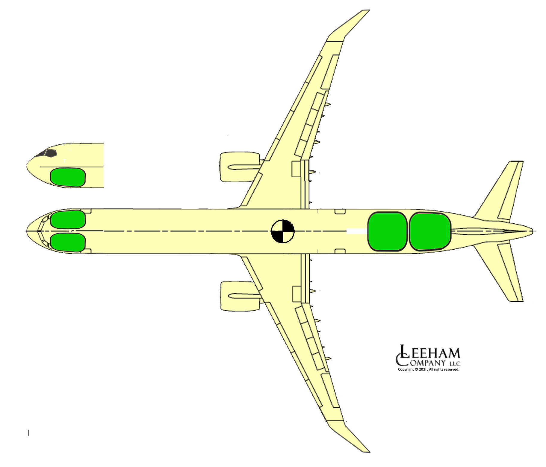
Figure 1. Typical placement of hydrogen tanks. Source: Leeham Co.
The hydrogen tank system
As discussed before, liquid hydrogen (LH2), which is cryogenically stored at -253°C, must have tanks that minimize the heat influx through the tank walls. The heat that leaks in will cause the LH2 to boil. At boil-off, LH2 absorbs surrounding heat, which keeps the rest of the LH2 below -253°C.
The tanks are made as close to a sphere as possible as this exposes the least surface per held mass of LH2. The tank is made as a Dewar vacuum flask with additional insulation on top (to limit the boil-off, should the tank lose its vacuum), Figure 2. The boil-off in a well-designed tank would be below one percent per day.
The tank holds a mixture of LH2 with H2 gas on top. It has a fill pipe (D) and an LH2 propulsion system feed (E). To keep the pressure low (at about 1.2 bars), the gaseous H2 is piped out of the tank via a pressure-regulation valve (A).
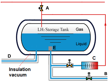
Figure 2. A principle schema of a vacuum flask LH2 tank.
LH2 is routed to the propulsion system (B) via pumps and valves. Before its usage in either a fuel cell or H2 burning gas turbine, it must be converted to a gas form in a heat exchanger at the propulsion system. The gas conversion is a performant heat sink that can be used by the propulsion system to manage heat problems. We will discuss this more in the propulsion system articles.
Fuel system and Auxiliary Power Unit, APU
To not vent the boil-off H2 to the atmosphere (which is entirely OK, H2 is a harmless substance), a hydrogen-fueled airliner will skip the noisy gas turbine APU and exchange it for a fuel cell APU.
Figure 3 shows a block schema for a hydrogen fuel system. The schema is taken from Airbus’ CRYOPLANE study report from 2003. We have modified it to show a three-tank system in the fuselage (called Passive tanks in the study) with engine feeder tanks (called Active tanks) close to the studies’ H2 burning gas turbine engines (we will look at both H2 gas turbine and fuel cell propulsion). We also replaced the studies’ gas turbine APU with a fuel cell one.
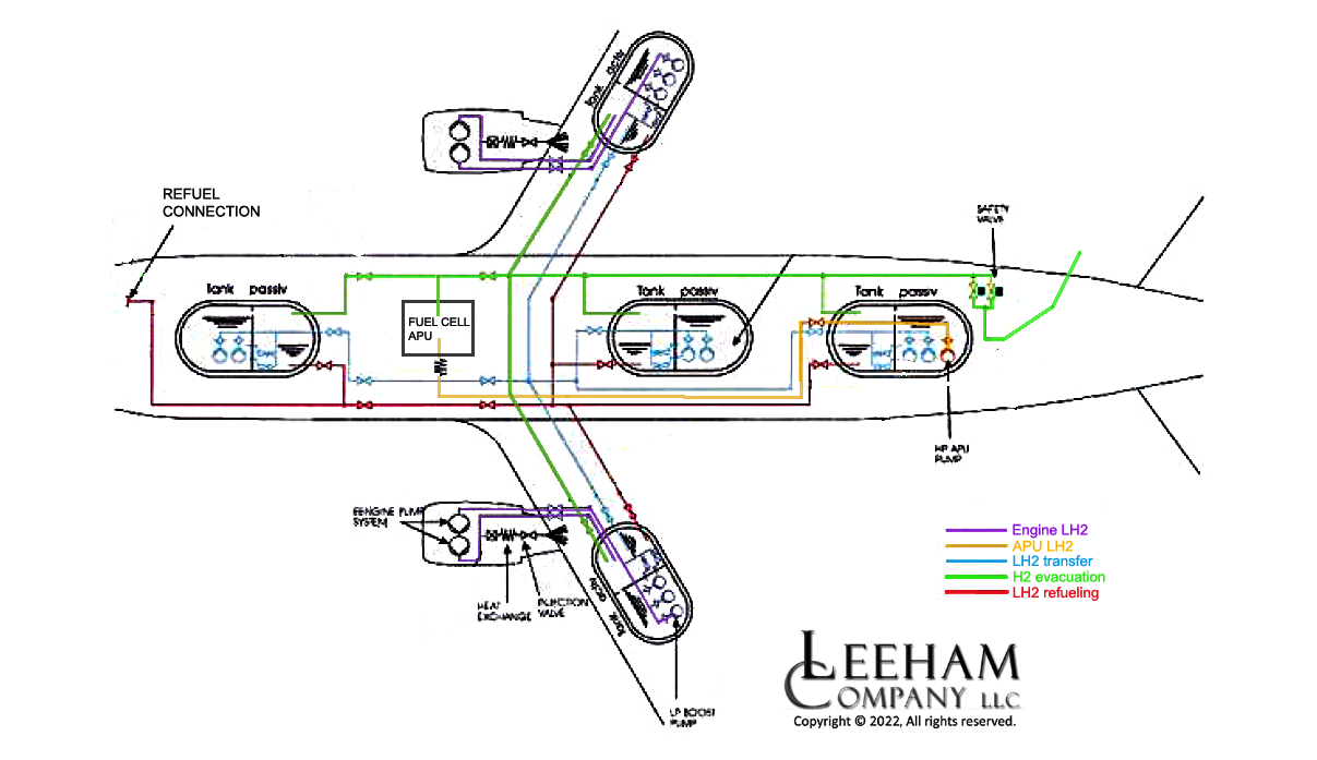
Figure 3. Modified LH2 fuel system schematic from Airbus’ CRYOPLANE study. Source: Airbus and Leeham Co.
A fuel cell APU has several advantages over a gas turbine unit:
- It’s virtually noise-free and can therefore be placed at its ideal place, close to the consumers of its services. A likely area is adjacent to the Air Conditioning Packs (part of the ECS, Environmental Control System) in the wing-to-fuselage fairing.
- It provides electricity to aircraft systems and oxygen-depleted air, which is an essential part of the hydrogen safety for the aircraft.
- A fuel cell produces more heat than electricity, which we will se in our propulsion Corners is a principal problem with a Fuel Cell alternative. In this case, the ECS can use the heat to warm the cabin when needed.
- The fuel cell APU produces water that can be used as cabin tap and WC water.
As a fuel cell APU doesn’t produce pressurized air (without adding a motor and compressor for this purpose), it assumes a “more electrical” aircraft system architecture like the Boeing 787 Dreamliner (where engine starts, de-icing, ECS air supply are all done by electric means).
With a fuel cell APU, the H2 boil-off is routed to the APU and not wasted in the atmosphere. Any additional H2 supply needed is added through a heat exchanger (C in Figure 2).
An LH2 fuel cell APU’s cooling and heating capability hints at gains with tight integration with the ECS in future LH2 aircraft.
Hydrogen safety
A hydrogen fuel system must meet the safety standards for airliner applications. Airbus CRYOPLANE study looked at the safety aspects and concluded:
Hydrogen poses its specific safety aspects to be considered in design and operation. However, the overall safety level will not be worse than for kerosene aircraft.
For the fuel system, some of the considerations:
- The long-term effects of cryogenic hydrogen on all components must be considered. Design standards and testing must verify these components’ safe functioning and life.
- The hydrogen tanks must be tested for what happens if they are penetrated by a fan or propeller blade or parts of a gas turbine disc. If the effects are dangerous, the placement of the tanks in the aircraft will be restricted to where no penetration is risked.
- As for a hydrocarbon-fueled aircraft, mixing the fuel and oxygen-rich air must be avoided in any closed compartment. Hydrogen leak detection is needed but not sufficient. Oxygen-depleted exhaust air from the APU fuel cell is thus routed to all closed compartments that contain fuel system components to eliminate the explosion risk.
With regard to the forward LH2 tanks in the illustration above, this UK concept has taken things a step further and introduced “pannier tanks” in elongated lateral fairings situated forward of the wing. An interesting design that saves fuselage space and that can counter c.o.g. issues with regard to weight distribution. Drag will increase, of course, but that may be outweighed by the benefits.
https://www.airport-technology.com/news/uk-hydrogen-driven-aircraft-concept/#:~:text=Aerospace%20Technology%20Institute%20%28ATI%29%2C%20along%20with%20a%20team,by%20ATI%20and%20sponsored%20by%20the%20UK%20Government.
The Hawker Siddeley Nimrod AS plane based on the Comet airframe was the the first in this area with a large under body pannier which held a radar scanner forward and torpedoes and sonar bouys behind. This was the best solution because of the Comets limited underfloor space which other maritime aircraft used. All modern aircraft use a pannier to smooth the aerodynamics between fuselage and wing and provide space for air-conditioning packs and such.
-One of the issues with under floor ballast/balance tanks in the nose and cheek style panier tanks is the additional safety safeguards required since the tank is no longer so well separated from the passenger compartment.
-Around the year 2000 many of the auto manufacturers such as Daimler Benz looked a fuel cells. The idea was to store the hydrogen as methanol or ethanol and convert this to hydrogen via partial oxidation. The US DOE proposed partial oxidation of pure synthetic iso-octane. Partial oxidation seems to be 85% efficient and probably more if gas turbine exhaust heat was used.
-Partial oxidation tended to produce too much CO and this ‘poisoned’ PEM fuel cells (it doesn’t effect SOFC) so the idea passed.
-Nevertheless something like this would allow an airliner to continue using wing tanks filled with liquid fuel as well as cryogenic hydrogen in the tail without resorting to nose tanks and pannier tanks.
-Once one goes to eletrofuels synthesis of methanol, ethanol and pure isooctane etc is straight forward and efficient.
–
–
>mixing the fuel and oxygen-rich air must be avoided in any planet compartment
What is a “planet compartment”? Or is that a typo and should read any “enclosed compartment”
Thanks, it was a typo in the first version that I corrected to “closed compartment..”
-Are there really plans to use a Dewar or vacuum insulated tank rather tank foam insulation? I would imagine the requirement would require very thick walls for the outer tank so that it doesn’t collapse inwards due to the vacuum? I suspect the only way would be through the use of Carbon Fibre Reinforced Composites. Such strength would make the tank crash worthy.
-It might be possible to develop sheet metal with a vacuum in between in a similar manner to some glass windows.
-The use of electric power from the boil of running through the APU fuel cells to operate a reliquification mini plant to convert some of the hydrogen back into liquid shouldn’t be ruled out since such liquefaction devices of about 1 litre per hour have been built. I would expect about 50% reduction in boil off due to the inefficiency of the fuel cell APU and the considerable energy required for reliquification. What helps is that the boil of is already quite cold.
There have been a lot of tank variants discussed over the years, since the 1980 investigations by NASA, documented in Brewer’s book, through the CRYOPLANE studies and all the work with space launchers and LH2. The consensus seems to be a Dewar vacum flask tank. The tank can be made of aluminum or CFRP. Both variants will be trialed by the Airbus teams working around the A380 demonstrator. For the failure case where the vacum goes bust, an additional layer of insulation is added on the outside of the flask to limit the boil-off rate. This is often described as a polyurethane or a superinsulator foam type.
-Thankyou very much.
-I’m curious about the possible use of variable sweep to adjust the centre of lift or trim for a hydrogen aircraft as the Centre of Gravity moves forward as fuel in the tail is consumed.
The Westland-Hill Pterodactyl IV of 1931 was a tailless design that used variable sweep to effect trim changes. The Bell X5, the first transonic aircraft to use in flight variable sweep, had to slide the wing position simultaneously to sweep changes to maintain trim. Certain technological advances I don’t understand allow wings to have variable sweep without a sliding mechanism.
Some very big swing wing aircraft have been built. The Rockwell B1 Lancer and Tupolev Tu 160 “Black Jack” both have more than twice the MTOW of an A321neo. It would only require variable sweep outboard of the engine pylons.
The’ winning design ‘ by Boeing for the U.S Supersonic transport ( 2707) had variable sweep also. And actually started to build one with a huge Wing box- Wing carry thru structure. (WCT ) Range problem surfaced as described by the locals
Full load halfway across the atlantic, or no load all the way. TheWCTwas to be made of Titanium. Eventually, and before the contract was cancelled, the ‘ double delta wing design was started.
The F-111was swing wing- and the WCT was basically D6AC Tool steel. Had production problems which surfaced when abusively drilled holes caused fatique issues and one was lost at low altitude in Nevada.
B1 Bomber used Titanium WCT and extra extra care re fastening with taperloks.
Having worked on 2707 and B-1 on the WCT along with other issues, IMHO the combined weight penalty of cryo tanks and ‘ swing wing ‘ structure for civilian use is a non starter.
I found an article on weight analysis for a B737-300 once and was surprised to find the tanks themselves weighed less than 600lbs.
However hydrogen has less than 40’% the weight of jet fuel so the overall weight should be much less.
Wings, at least outboard of the engine pylons, should become ‘dry wings’ and rather thin, stiff and light.
As far as your intuition that swing wings wouldn’t be worth the weight penalty I think we would need to do some calculations. I actually share your scepticism but have a gut feeling it could work.
I’m not sure where the hinge points should be. Either at the engine pylon, mid span or 2/3rd of the span along. It couldn’t be much worse than the B777-9 folding wing tips if at 3/4 span and might be used to reduce span at the gate much as the F-14 Tomcat over swept its wings to reduce deck space.
It would provide the perfect trim and rather a gentle landing. The alternative is under floor tanks in the nose, panier tanks or dorsal tanks which introduce smaller tanks distributed around the fuselage.
I have fond memories of the F-111C . It was a monstrous beast with a 3000mi+ range and gave the RAAF power to interdict all over the pacific and maintained order and peace there for a long time. Fast enough to burn of its own paint. There must have been something about the swing wing that worked with those engine.
The APU might be the best place for fuel cell as a Toyota Mirai size unit is sufficient for a narrowbody. Often you can make good use of the cold LH2, stream from the fuel cell, nitrogen after oxygen is consumed and heat both in aircraft and engine systems/components. Just the engine fuel/oil cooler can be replaced with a much smaller LH2/oil cooler, turbine case cooling and active cleance control systems can shrink, especially HPT nozzle guide vanes cooling air and HPT blade cooling air benefits alot from beeing much cooler. Engine bearing compartmen cooling can also be made much simpler having LH2 available and used directly or thru an intermediate Helium circuit. I think PWA is full stream calculating where it will reduce size, cost and allow cheaper materials, the risk is that they go too far including compressor hub and casing cooling and use LH2 for bearing lubrication instead of oil..
Reserves/ reliability probably mean the 114kW Mirai sized fuel cell when downsized for aviation use might only be 1/3 of that. Who knows how it does at ‘altitude’ in emergency
The standard PW APS3200 used in A320 series develops 90kVA ( roughly equivalent to kW) . More electric aircraft require even greater power as PW APS 400 gives 450kVA for Dreamliner
It is engine start that consumes the most Amps. Restart at altitude get help from windmilling and inlet pressre recovery at speed. It will take time to test and derive all certification requirements and define certification tests with pass/fail criterias for the whole system, especially if the fuel cell is placed in the wingbox area. It needs to avoid any engine disk burst fragments puncturing the fuel cell, tanks and tubing with valves or statistically acceptable risks if sensite systems placed in the “danger zone”. Hence it will take time since no military aircrafts with fuel cells to learn from.
The benchmark that automotive manufactures want to achieve for PEM fuel cells is 6kW/Litre which tends to lead to 6kW/kg. Mirai I think is getting to around 4. However several labs have achieved over 6KW/Litre. It’s only a matter of time.
One can imagine that the starter motor/s for the turbofan will be on the main shafts and will never actually be switched since it may make sense to add power into them continuously since the Fuel Cell APU can be left on continuously.
An idea Rolls Royce looked into in its more electric engine was to have a super conducting motor-generator acting as a reduction gear. For instance a 2 Pole generator and a 4 pole motor would achieve 2:1. The technology for the superconductors seems to be there allowing these small motors to be produced.
The inverter could inject power in acting both as reducer, starter and hybrid propulsion.
Have to wonder if water recovery is worth all the monkey motion of collection network and pumps?
What is the weight difference between an equivalent KW APU and a Fuel Cell.
And is the tight integration costs and ensuring no freezing of pipes and heat to the right places worth it?
In my experience, the super efficient systems had a super high tech cost that the lower tech stuff did not. Our only answer was to have at least 3 or more higher tech so we cold afford the loss of one (or two) while we got the super special factory tech who often could not answer what the issue was.
Since the oxygen depleted air is to be used as an inerting atmosphere around the fuel tanks I would think it would need to be dehydrated anyway. Plus I think the water generated if stored in the furtherst part of the tail (along with any subsequent sewage) is a good ballast against the CoG moving forward as the rear placed tanks contents are consumed. Each kg of hydrogen consumed by the fuel cell should make 16kg of water.
Wonder if a very old method of storing high pressure air ( 2000 psi ) in lightweight tank(s) as used on an early missile designed by JPL in the 50’s would be worth considering. Basically a cluster of 4 inch diameter aluminum tubes linked together was used to pressurize fuel and oxidizer tanks for a 20,000 lb thrust rocket motor on the ‘ corporal’ missile. ( US M2 corporal missile ). perhaps such could be used in the wings with careful design also