Leeham News and Analysis
There's more to real news than a news release.

 Leeham News and Analysis
- A350-1000 or 777-9? Part 3 April 25, 2024
- Boeing CEO promises company is turning around…again April 24, 2024
- Solid start for stand-alone GE Aerospace despite cuts to LEAP output April 23, 2024
- SPEEA, Boeing at impasse over safety program, union says April 23, 2024
- Better transparency needed on Boeing’s 1Q earnings call April 22, 2024
Bjorn’s Corner: Sustainable Air Transport. Part 21. Fuel Cell system design

By Bjorn Fehrm
May 27, 2022, ©. Leeham News: Last week, we looked at the power levels we need in a fuel cell and electric motor system. We listed the required powers and durations for takeoff, climb, and maximum continuous power levels for a 70-seater turboprop.
Now we go deeper into the fuel cell system design, looking at system powers and thermals.
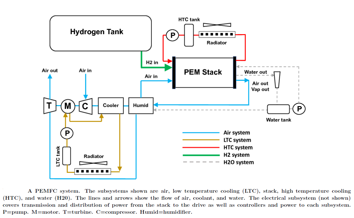
Figure 1. The principal parts of a fuel cell propulsion system. Source: NASA.
Liquid hydrogen fuel cell system
We have previously looked at the components we need in a fuel cell system, Figure 1. To discuss the sizing of such a system over the different phases of flight and how all the various components behave is complex. It’s a system with a lot of moving parts.
Figure 1 is taken from a NASA report (you find it here) that discusses an aeronautical fuel cell system that uses gaseous hydrogen. Consequently, it doesn’t use the cooling capacity inherent in an LH2 fueled system. We have previously shown that a gaseous hydrogen tank system has unacceptable mass and volume characteristics for an airliner. For our liquid hydrogen-fueled 70 seater turboprop, we want to discuss a cryocooled fuel cell system.
For this purpose, we use a recent report from a team from the Norwegian University of Science and Technology (NTNU) where a liquid hydrogen fuel cell system is described and simulated. You find the NTNU report here. It uses the LH2 to cool the power cables, inverters, and electric motors to superconducting status. As a result, the power losses and masses for these parts are reduced to a fraction of a non-cryogenic system.
The NTNU report observes that the components in such a system are in their early stage of development (low TRL level). It simulates a system ready for prime time by 2035. To cater to system uncertainty it simulates a base case, a conservative variant, and an optimistic scenario. We use the base case.
Figure 2 shows the system which uses the LH2 cool sink to turn the power cabling, inverter, and motor to superconduction. Note the blue flow path of the LH2, which goes from LH2 at 20K, vaporizes at 22.164K (by it absorbing 0.44MJ/kg of heat), and then flows backward in the system, cooling each major component until it has the required 358K (85°C) for the fuel cell entry. LH2 absorbs about 12kJ/kg and K after vaporization.
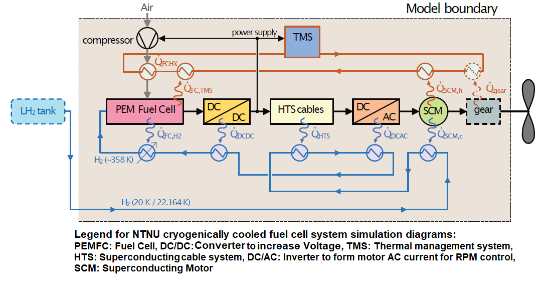
Figure 2. The block diagram of the LH2 fuel cell system modeled by NTNU. Source: NTNU report.
The red cooling path is a classical liquid (water/glycol) additional cooling system to top up where the LH2 cooling is exhausted. In practice, the blue cooling is done with a Nitrogen system as hydrogen is difficult to handle inside the system units. The liquid hydrogen transfers its cooling capacity to this system in a heat exchanger before entering the fuel cell as 85° H2.
The system’s power flow and heat losses are shown in Figure 3.
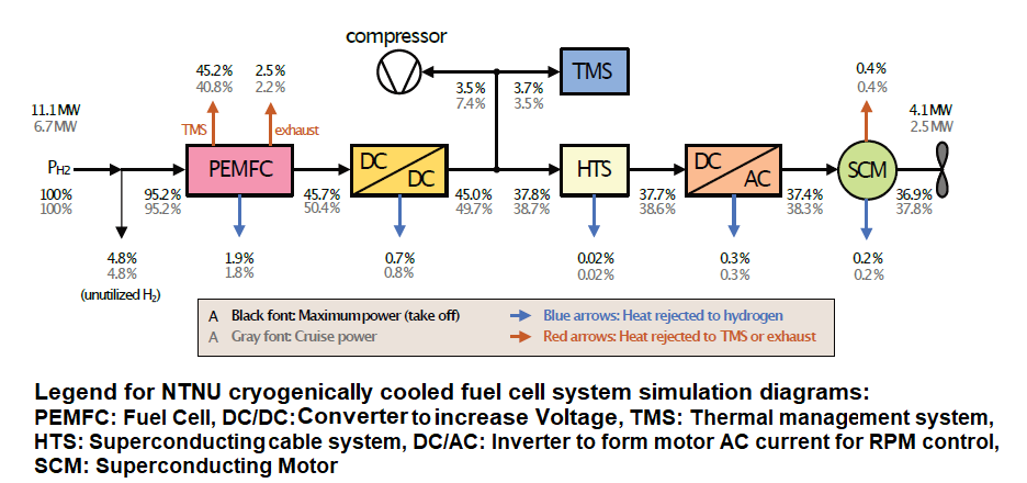
Figure 3. Power levels and heat dissipations for the system. Source: NTNU report.
The black notations are for power/heat flows during takeoff, where the report assumes 2.05MW shaft power per side, and grey values are for the cruise at FL200, where 2*1.25MW is assumed.
Observe the enormous losses. For takeoff, we need 4.1MW shaft power for the propellers. The system draws 11.1MW LH2 from the tank. 4.8% of the 11.1MW leaves as unused H2. The remaining 6.47MW is absorbed by the blue and red cooling systems.
As discussed last week, the system can be designed to absorb takeoff and the initial climb heat losses but must be sized for the losses from continued climb and cruise.
At cruise at FL200, the system draws 6.7MW LH2 and delivers 2.5MW shaft power. 4.8% leaves as unused H2 as before, and we need to cool away 3.85MW. The 3.85MW and any additional heat generated during the climb to cruise size the heat management of the system.
Note the minimal heat the hydrogen cooled DC/DC converter, HTS cabling, DC/AC inverter, and SCM motor generate. The simulation does not analyze the emergency cases where the superconduction is lost for these units.
System efficiency
The overall system efficiency is defined as shaft power out versus power drawn from the tank. It’s on average 38.6%. The fuel cell enthusiast will say the fuel cell is closer to 50%. Correct, about 45% at a cruise load, lower at takeoff, and higher when not stressed (depends on the fuel cell sizing). But we are not looking at component efficiencies. What is to compare with an alternative propulsion system is the shaft power generated to the propeller/fan to the power drawn from the energy store.
In the report, NTNU discusses the possibility of cutting the top power of the system (and thus heat) by using a battery as an energy source, Figure 4.
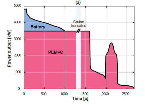
Figure 4. The idea of cutting the top power need by using a battery energy store. Source: NTNU report.
The NTNU team probably make the same mistake we discussed in the hybrid articles. If the battery-assisted power levels are needed for emergencies (for example 100% power for an early go-around), the batteries cannot be used for other purposes during the flight; thus, the fuel cell must be sized for the full load.
Next week we use the NTNU and the NASA reports to look at what happens should we not have LH2 at -253°C to aid our system’s cooling.
I read this article today – Shrinking battery density is coming https://inhabitat.com/tesla-unveils-details-of-a-100-year-battery/
Multiply it by 10x more when you want to use it a plane.
Then theres the Tesla exaggeration factor , make it another 20x or 30x when they want to bump the share price
Then the author of the story is a ‘travel writer’ who has no technical expertise but likes looking for vegan food to eat…right
First
This kind of “breakthrough” articles are the jour the day since 2015 (there are about 10 of them per year). In these seven years, the actual SYSTEM energy density for flight batteries has gone from 120Wh/kg to 170Wh/kg, a 42% increase, i.e. 6% per year. There are no signs this will speed up.
Second
The Tesla battery cells are different from what’s needed for electric aircraft and VTOLs. The car industry wants maximum energy and can compromise power delivery (called C rate for cells). We need power (C rate) and can therefore not benefit from the quantity and energy capacity the car industry generates. Our cells come from the cell manufacturers’ Power Tool lines.
Is the cell working at atmospheric pressure? I ask because if it were to operate at a higher pressure, then the exhaust (carrying 40%+ of the original energy input) need not be wasted. It can be put through a turbine and some of the energy recovered. Just like a gas turbine, the higher the pressure ratio, the more efficient it is.
Hi Chris,
this is done in the NASA report but not in the NTNU. Download both and find the arguments for and against. In the NTNU case, the out pressure is 1.6 bar and it’s not worth the complication with a turbine to recover the pressure versus the outside air if I remember correctly.
Yes, if it is enough heat energy it can be made to produce thrust, the natural choice would be to augument the electrical motor cooling fan with a compressor and heat input from the fuel cell probably thru a heat pump and let the turbine drive both the cooling/power fan and compressor and have the exhaust produce some thrust. Even the P-51D oil cooler was said to produce thrust thru its shape and heat input. Today one would 3D print this machine from a few parts.
The P-51 combined the smaller oil radiator with the larger glycol engine radiator in the same duct – but different exit doors .
It may not have had ‘all the effect claimed’ as to get a smooth airflow it required a long duct and the not so efficient cores of the 1940s
The effect was named after FW Meredith who developed the maths in the mid 1930s
https://www.kitplanes.com/the-meredith-effect-fact-or-fiction/
In theory the same as nuclear powered jets, where you use the heat circuit to heat the compressor exit air in the “combustor” thru an heat exchanger. It boils down to how much heat vs. cost and mass of a 3D printed engine with a highly efficient heat exchanger
What is interesting is if the High Temperature HT-PEM fuel cell which Bjorn mentioned which operates at 180C becomes possible. In this case the heat will be at a temperature suitable for Jet Thrust “Meredith Effect” recovery. The LT-PEM at 80C less suitable.
The whole “Meredith Effect” thing has a bit of nationalism attached to it. Spitfire, P-51, Me 109F (which had boundary layer splitters).
It could properly be called the “Junkers effect” as Junkers patented the diffusor-radiator-jet combination as “Düsenkühler” (‘jet cooler’) in (Deutsche Reichs Patent) DRP 299799 on 17 January, 1915. (Von Gersdorff et al., “Deutsche Flugmotoren und Strahltriebwerke, p. 196.)
The principle obviously was well-known in the English-speaking part of the aviation industry as well. “Fundamentals of Fighter Design” by Ray Whitford notes (p. 61): “In 1926 it was realized that airflow through the radiators on liquid-cooled engines could, if properly ducted, eliminate the cooling drag and even produce a little thrust at speeds above 260 kts (483 km/h).”
The German magazine “Flugzeug Classic” in an early issue quoted from a speech given by Professor Willy Messerschmitt in the late 1930s in which he praised the Junkers “jet cooler” as the most important single contribution to high speed flight as it cut down the otherwise prohibitive cooling drag, pointing out that the most advantageous way to incorporate the concept in a high-speed aircraft was in the form of wing radiators. (The Me 109D with the Jumo 210 had a chin radiator and when the larger DB601 engine came in received Jet Cooler radiators which would be called Meredith Effect Radiators.
René Lorin (24 March 1877 – 16 January 1933) was a French aerospace engineer and inventor of the ramjet.
Isn’t the Meridith Effect just a subsonic ramjet?
In 1908 Lorin patented the first subsonic ramjet design. He published the principles of a ramjet in articles in the journal L’Aérophile from 1908 to 1913, expressing the idea that the exhaust from internal combustion engines could be directed into nozzles to create jet propulsion. He could not test this invention since there was no way at the time for an aircraft to go fast enough for a ramjet to function properly.
When René Leduc applied for a patent on a ramjet design in 1933, he discovered Lorin’s publications and tried to contact him, only to learn that he had recently died. Leduc thereafter paid homage to Lorin’s work.
The subsonic ramjet that Lorin conceived, which is also known as an athodyd (aero thermodynamic duct), is an air breathing subsonic jet engine in the form of a continuous duct that uses the engine’s forward motion in conjunction with its shape to compress incoming air. Fuel is added to the compressed air, ignited and the resulting hot gas accelerated through a nozzle, producing thrust. Replace the fuel with a radiator and you have Meredith Effect.
The concept lay essentially dormant until WWII, at which time Eugen Sänger and Irene Bredt (Designers of the “Silverbird” space plane realized that by using high combustion temperatures in a subsonic athodyd, practically unlimited performance with fuel consumption values between gas turbines and rockets might be possible.
Hugo Junkers was a personal hero.
Yes. Apparently the chief aerodynamicist for the P-51 project said much later ( and contradicted Lee Atwater later head of North American) he hadnt even seen Meredith’s technical paper at the time and the ducted system included in the design was based on ‘well know aerodynamic principles’
The reduction in drag achieved to a very minimal level was very useful, ‘additional thrust’ was hard to measure in practice and probably unlikely.
For Junkers, it was accident of history that they were mostly based in the eastern part of the Reich- thus later in the Russian zone- otherwise his business and name could have lived on and formed the nucleus of the West German aviation industry
Once the loss or the efficiency and the weight are included, that’s not going to work.
The production of cryogenic hydrogen through electrolysis and then liquefaction is probably getting to about 70% efficiency at present (having risen from 60% only a 20 years ago) and it may reach 80%. The cooling effect clearly will assist in recovering some of the liquefaction energy costs. Perhaps that in itself will promote even smaller aircraft to use cryogenic hydrogen. I’m optimistic about small scale liquid hydrogen.