Leeham News and Analysis
There's more to real news than a news release.

 Leeham News and Analysis
- Boeing unlikely to meet FAA’s 90-day deadline for new safety program April 18, 2024
- Focus on quality not slowing innovation, says GKN April 18, 2024
- Boeing defends 787, 777 against whistleblower charges April 17, 2024
- Dissecting Boeing CEO’s statement next new airplane will cost $50bn April 15, 2024
- Bjorn’s Corner: New engine development. Part 3. Propulsive efficiency April 12, 2024
Bjorn’s Corner: New aircraft technologies. Part 12. Airframe efficiency improvement

By Bjorn Fehrm
May 12, 2023, ©. Leeham News: This is a summary of the article New aircraft technologies. Part 12P. Airframe efficiency improvement. The article discusses the different drag types that affect an airframe, their magnitudes, and the physics behind them. Airframe efficiency improvements are about reducing these drags.
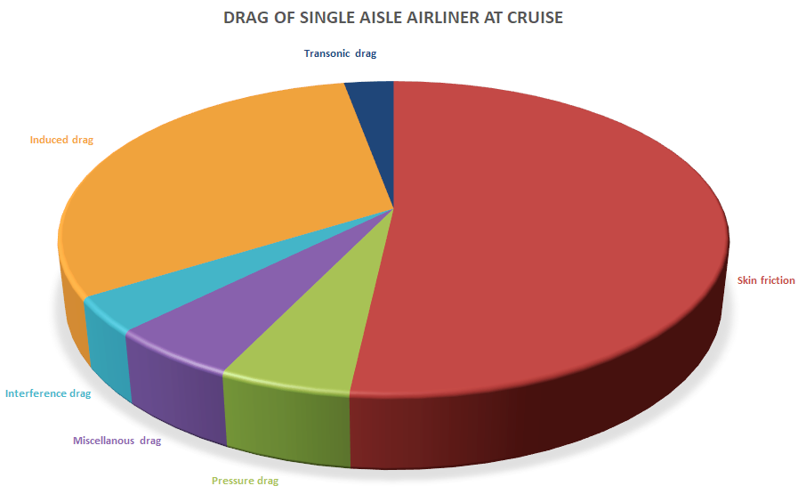
Figure 1. The drag types that affect our single-aisle airliners. Source: Leeham Co.
Reducing the drag of an airliner
To increase the airframe efficiency of an airliner, we need to reduce the drag of the airframe. Figure 1 shows the drag types that affect a typical single-aisle airliner and their portion of the total drag.
We can divide the drag types into three buckets:
- Drag due to size. In aero speak, we talk about the largest portion of parasitic drag, the friction drag, which is over half the aircraft’s drag. Ìts magnitude depends on the type of friction drag (laminar or turbulent) and the total friction area of the aircraft, called the wetted area.
- Drag due to weight. In aero speak induced drag. It’s due to the global air circulation from under the aircraft and wing to its overside, Figure 2. The drag level is dependent on the aircraft’s weight, its wingspan, and the pressure distribution along the span.

Figure 2. The global flow of air from the aircraft’s underside to the top of the aircraft. Source: Google Images.
- Apart from these two dominant drags, we have smaller contributions as part of Parasitic drag from pressure drag (drag due to form) and interference drag (drag due to air being squeezed). Finally, we have transonic drag (parts of the airframe have supersonic flow pockets).
Airframe designers have worked to reduce these drag types for the last 100 years. We will go through them and discuss what has been done over the years and what modern technology and new ideas can do to reduce their size.
We start next week with Drag due to size, air friction drag.
Interesting, I like this series, thanks.
There is drag due to gaps, not perfect fit landing gear doors or no landing gear doors, windsheild wipers, small fwd facing steps in the nacelle and noise reducing grooves, small air intakes like for Air cycle Machine coolers, antennas like SATCOMM, coolers like bleed air coolers, Flight speed is a big factor. More efficient airport handling and you can cut flight speed for the same arrival time. Ideally your pilot pick you up at the nearest UAM helipad and lands next to the airliner he will fly. You just climb the stairs after him and turn right into your biz class seat.
Miscellanea (except for the flight speed stuff you mention).
It’s included in the pie chart.
Some is in misc and some like the windshield wipes is parasitic. Domes I think are a combination of parasitic and induced.
TW,
In the vast majority of textbooks used by UW Aero/Astro in the late 80’s, when I attended, all the various drag sources besides Induced were lumped into the Parasitic category. In fact Parasitic Drag was defined as the Total Drag on the airframe minus the Induced Drag. This makes a lot of sense because Parasitic Drag provides no benefit, it just sucks energy from the system. On the other hand, Induced Drag is a consequence of Lift. Lift is useful, so the drag associated with it is not considered parasitic.
Bjorn has chosen to account for the drag in three main categories instead of just two. He is breaking Skin Friction Drag out as a separate category and is calling it Parasitic Drag. This is different from the “classical” accounting that I mentioned above. Then he is lumping other, non-Skin Friction Drag, parasitic sources together into a third category.
So, according to the “classical” view, the drag sources that Claes mentioned would all fall under Parasitic Drag.
It migt be worth looking at those and come up with smart solutions. The WiFi Satcomm aft body antenna looks like it could be integrated into a new aircraft. In aero and structures design one can see the development at Gulfstream going from the heavy and pretty rock solid G5 familty to the new G700/G800. Once you just go for range at min mass you will get sensitive thoroughbreds.
The latest G400/500/600 are different fuselage diameters ( flattened oval) to the larger G650/700/800 models
A good example of the family series of aircraft the the smaller series having the same fuselage ( but wider than the original GIII/IV/V type) of different lengths , but same PW800 engines ( based on GTF core) and wings
The larger longer range models use RR Pearl and a different wing and the fuselage is wider but not much extra height
A way to work on a double aisle flattened oval fuselage than could have smaller upper panels to make a single aisle development down the track. Engines, wing spans, and MTOW tailored to suit.
Claes,
I agree that all those drag sources should be investigated, understood, and minimized using smart solutions like you say. It seems like the WiFi Satcom blister would be low hanging fruit, but it could be more complicated to integrate than any of us realize.
It looks ugly but are way back on the fuselage hence having the boundary layer growing quite a distance before the airflow having to make a detour around it so the benefit might be small on todays airliners. With a tail fan to reenergize the boundary layer the situation changes. You look at the flat cockpit windows and wonder if not curved ones could generate less drag, like having small air/hot water jets instead of wingshield wipes would be a natural development. One could think flying “clean” on contious decent at flight idle without speed brakes and lowering the gear less than a minute from landing would lower emissions/noice if you are free to select between a few approach speed/profiles.
I think the pie chart needs some conditions.
Think a typical airfoil in an airstream with a certain drag. Now rotate that airfoil 90 degrees.
Not sure if (the same) skin friction/ wetted area accounts for half the drag now.
The conditions are stated there: single aisle airliner at cruise.
No need to invent irrelevant conditions
The cruise condition is not specified in this article. However, Bjorn might’ve mentioned in previous articles that he was going to focus on cruise.
*Cruise* is on the captions for the pie chart
Oh, I see it finally. Not in the figure caption but in the chart title. Thanks.
Of course, that is the reason for the large percentage of Skin Friction Drag.
We had some of the theory in flight school but it did not get into these depths so its very interesting to see it delved into.
Fluid dynamics is a serious deep and intense school and other than some obvious aspects, just watching as an observer.
Just saying this graph is for a specific application (NB) not a general guideline.
E.g. if you would build more stubby, heavy fuselage with the same wetted area, skin fraction could be a much lower percentage.
keesje,
If the stubbier fuselage has the same wetted area as the NB one, then the Skin Friction Drag will be very close to the same. This is because Skin Friction Drag scales with the wetted area.
A heavier fuselage would require a higher Lift and therefore a higher Induced Drag, so the Skin Friction Drag would be a lower percentage of the total. But because you specified that the wetted area be the same, this percentage shift is because of the increased weight, and not the stubbieness, i.e. differences in the fineness ratio.
I think for a shorter stubbier fuselage likely pressure drag (drag due to form), interference drag (drag due to air being squeezed), and transonic drag (parts of the airframe have supersonic flow pockets) would probably be higher, next to higher lift induced drag. Despite the wetted area / skin friction staying roughly the same..
Oval fuselages IMO better work vertically (e.g. double bubble) because you can use floors to handle (some) atmospheric pressure induced loads. If you don’t want structure in the cabin, additional structure / weight in the fuselage become unavoidable (induced drag) for horizontal oval fuselages.
keesje,
I agree in principle with what you said above:
“I think for a shorter stubbier fuselage likely pressure drag (drag due to form), interference drag (drag due to air being squeezed), and transonic drag (parts of the airframe have supersonic flow pockets) would probably be higher, next to higher lift induced drag. Despite the wetted area / skin friction staying roughly the same.. ”
However, form drag, interference drag, and transonic drag (compressibility effects) are relatively small contributors compared to skin friction and induced drag, probably not enough to move skin friction drag away from about 50%.
Also. I agree with the issues you cite when considering vertical oval vs. horizontal oval fuselages. But, reducing the skin friction drag by paying for a little bit more induced drag might not be a bad trade if other benefits are large enough.