Leeham News and Analysis
There's more to real news than a news release.


Bjorn’s Corner: Faster aircraft development. Part 15. Detailed Design of Structures

By Bjorn Fehrm and Henry Tam
November 7, 2025, ©. Leeham News: We do a series about ideas on how the long development times for large airliners can be shortened. New projects talk about cutting development time and reaching certification and production faster than previous projects.
The series will discuss the typical development cycles for an FAA Part 25 aircraft, called a transport category aircraft, and what different ideas there are to reduce the development times.
We will use the Gantt plan in Figure 1 as a base for our discussions. We have now entered the Detailed Design phase, where we use the Airframe structure design as an example of the work during this phase.
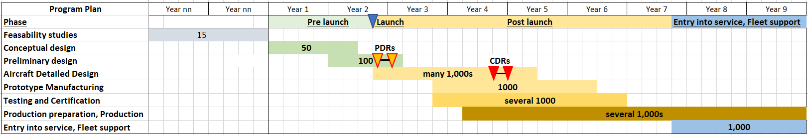
Figure 1. A generic new Part 25 airliner development plan. Source: Leeham Co. Click to see better.
*** Special thanks to Paul Smith for helping with this article ***
Detailed Design of Structures
We showcased some of the programs’ Systems aspects when covering Conceptual Design and Interiors during Preliminary Design in Parts 8 and 11 of this series. For the Detailed Design phase, let’s use Structures as our deeper dive study.
Here are a couple of terms (as defined by the FAA) you may see in this article:
- Limit load is the maximum load of an airplane structure to be expected in service.
- Ultimate load is the limit loads multiplied by a prescribed factor of safety, often 1.5.
Prior to Detailed Design
The Structure teams finalized their design concepts during the last phase, completing the outline of the aircraft and the layout of structures. Interfaces have also been defined and agreed upon. Using the updated loads generated by the engineering sciences team, structures teams can now start to design components in this phase.
Considerations for manufacturability and maintainability have been addressed as input to the detailed design of the structures. In addition, certification requirements on the structures have been confirmed with the relevant authorities. Suppliers, in theory, can return to their home site after Preliminary Design to conduct Detailed Design work because they should have all the information required for the head-down work.
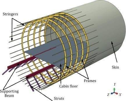
Figure 2. The main parts of a typical fuselage structure of an airliner. Source: Google Images.
Detailed Design Phase
The Detail Design phase continues the development of the Preliminary Design solution by generating production drawings that define the design of all aircraft parts.
The main activities during this phase include:
- Managing the program and project.
- Producing the product definition to a detailed level.
- Conducting compliance planning.
- Supporting product development.
There may be additional activities, such as a weight reduction program, if the preliminary design solutions do not meet weight targets (which they often don’t). The Critical Design Review (CDR), which we will discuss later, is an important checkpoint of this phase to confirm the aircraft design’s maturity.
Compliance Planning
With the Certification Basis defined in the last phase, the team now needs to expand on the Certification Plan. A Certification Plan, at a high level, is a document that presents how the Type Certificate applicant intends to show compliance with applicable regulations. For example, the FAA Part 25 Airworthiness Standards states:
- 25.307 Proof of structure.
(a) Compliance with the strength and deformation requirements of this subpart must be shown for each critical loading condition. Structural analysis may be used only if the structure conforms to that for which experience has shown this method to be reliable. In other cases, substantiating tests must be made to load levels that are sufficient to verify structural behavior up to loads specified in § 25.305.
(b)-(c) [Reserved]
(d) When static or dynamic tests are used to show compliance with the requirements of § 25.305(b) for flight structures, appropriate material correction factors must be applied to the test results, unless the structure, or part thereof, being tested has features such that a number of elements contribute to the total strength of the structure and the failure of one element results in the redistribution of the load through alternate load paths.
What are some acceptable ways to show compliance with 25.307(a)? Could it be done by analysis only? Maybe. Yet, the OEM needs to have relevant experience and be able to demonstrate that their analysis method is reliable. Otherwise, analysis and testing are required.
The text in the airworthiness standards is pretty generic. What does “[s]tructural analysis may be used only if the structure conforms to that for which experience has shown this method to be reliable” mean? This is when guidance materials, such as Advisory Circular (AC) 25.307-1, could help. For instance:
CERTIFICATION APPROACHES.
The following certification approaches may be selected:
- Analysis supported by new strength testing of the structure to limit and ultimate load.
- Analysis validated by previous test evidence and supported with additional limited testing.
- Analysis supported by previous test evidence.
- Test only.
The Advisory Circular goes on to provide more details on each of these approaches. If the guidance is insufficient, the team would need to develop proposals and negotiate the means of compliance with certification authorities. We will go into more details on compliance planning in the next article.
Program Execution
Structures teams need to produce and release many datasets during this phase . They need to continue to refine the solution from Preliminary Design down to every detail part, nut, and bolt (there are in total about three to four million parts in the aircraft, many of these trivial like rivets or fasteners, but we count thousands of structure parts).
Datasets for assemblies, components, sub-components, etc., need to be produced and released to enable parts production. There are also many documents to be released. Stress report and weight status report are examples.
In addition, structures teams need to work very closely with suppliers to ensure that datasets are released in the right sequence to support tooling development and to procure long lead-time items. Parts such as the wing skins often have a very long lead time due to their manufacturing process. The wing skin dataset, as a result, needs to be released earlier than some other datasets, or the team needs to use a workaround process to initiate the order.
Managing change is critical during this phase. The team needs to carefully evaluate changes to recognize upstream and downstream impacts. For example, if an interface needs to be modified at this stage, it could impact other structures, systems, or interior. There is usually a change board that approves and controls changes. If a change is deemed necessary, the team needs to coordinate the work with other teams and minimize the impact on parts production, test articles assembly, and tests.
Risk management is another important topic. Technical and program risks should have been identified in the Preliminary Design phase. During this phase, the team needs to monitor these risks. If a risk materializes, the team would need to execute the appropriate mitigation plan. For instance, the weight of a component exceeds its target because of an optimistic assumption. If there are sufficient design margins, this may not turn into a big issue. However, if there are insufficient design margins, design changes may be necessary.
Test Planning
In the program’s next phase, extensive testing will be conducted to demonstrate that the design meets the specifications. In preparation, engineers need to develop test plans and obtain approval from authorities during this phase. In parallel, they need to finalize the design and begin setting up the test facility so mechanics can assemble test articles as soon as parts arrive, allowing tests to kick off as soon as practical.
An Interesting Note
Structures are part of the overall aircraft system but do not follow the same design process as systems such as hydraulics, electrical systems, flight controls, and so on. However, structural engineers still need to design to requirements and go through verification and validation.
Structural requirements come from regulations, product features, and technical needs. We have illustrated regulatory requirements in the previous section. So, we are not reiterating it.
Product-related requirements usually originate from market requirements. These requirements flow down to aircraft-level requirements and then to structural requirements. For example, an aircraft level requirement can be the design service goal is 50,000 flight cycles and 75,000 flight hours. This becomes a structure’s durability requirement. A follow-on technical requirement could be that the design service goal shall be demonstrated by analysis and tests that catastrophic failure will not occur during the aircraft’s design service life.
Another example is service ceiling and cabin pressurization. For instance:
- The aircraft service ceiling shall be 41,000 ft.
- The cabin altitude at the service ceiling or below shall be less than or equal to 6,000 ft.
These become structural requirements for the pressure load cases applied to the fuselage, doors, windows, etc.
Structures teams also do not conduct functional hazard assessments, system safety analyses, common-cause analyses, and so on. When designing structures, engineers use qualified materials with proven properties to design the airframe. Representative articles are then tested to ensure analyses correlate well with test results, supporting the validation of analytical methods. These validated methodologies can then be used to make predictions. This is why new structures almost always require analyses supported by tests.
Additional Work for Start-Ups
Imagine the development team has an unlimited range of nuts, bolts, bearings, connectors, and so on to choose from, and the team can select the optimal part for their specific design. This has the potential to yield a very lightweight design. Yet, it would be difficult, if not impossible, to manage from supply chain, manufacturing, and customer support perspectives.
To address this issue, a start-up would need to develop a standard parts catalog so that the team could reuse standard parts to help optimize the inventory, simplify the “3D puzzle” on the production line and in the field, and take advantage of the economies of scale.
This should be done before Detailed Design to facilitate the design process. In addition, the team should develop design guidelines. Guidelines help engineers to use common solutions and apply best practices, minimizing wasted effort on reinventing the wheel. For example, these documents could include guidance on finishes, protective treatments, metal forming processes, etc. They could also include best practices such as machined fillet radii. Again, these documents should be developed in earlier phases so that the team can refer to them in this phase.
Speeding Up the Detailed Design of Structures
The standard parts concept is not new. Mature OEMs already have their standard parts catalogs. If an OEM takes this to the next level by including “standard” brackets, clips, etc., it will save time and cost. For instance, a designer can choose a bracket based on desired attributes from a database. This reduces the number of hours spent on design and analysis. If these brackets can also be used across different programs, there is potential to reduce costs by producing more of the same parts. It’s been difficult to achieve this when using traditional drawings in the past; modern PLM system facilitates this approach.
A mature Preliminary Design Review, with input from all functions, can help accelerate the Detailed Design phase. If there are many design change requests upon exiting the Preliminary Design phase, the team would need to address them before going full speed on detailed design. This could slow down the structures teams and other teams dependent on their output.
But, having high-quality exits is harder than it seems. Incentives often encourage participants to hit a milestone on time. Yet companies need to ensure these incentives do not motivate managers or partners to defer work or accept immature products. Technical debt, just like financial debt, requires interest payments.
Thanks Bjorn, Henry, and Paul for another good article.
Compliance planning is pertinent to the 777X predicament (although with regard to much more than structures). Boeing created the compliance plan under one set of expectations from FAA, but it’s now being carried out under a different set.
It’s clear from these articles why that would cause significant additional workload near the end of the project, as documentation now required may never have been addressed or developed during earlier phases, according to the original compliance plan.
To go back and develop that documentation for existing components is time consuming, and requires coordination with suppliers as well. That’s why it’s difficult to certify an aircraft after the fact. The farther into development you are, the more difficult it becomes.
Then the “boring job” of calculating/deciding tolerances both form and position as needed so structural analysis can be for the worst combination. You also have tolerances as part comes out of autoclave or press tools. You have to add margins for manufacturing defects that pops up (like oversize rivets) and in service repair allowances and not just copy blueprint tolerances on both primary and secondary structures. Aircraft aluminium alloys needs protection from corrosive liquids (like below toilets, salty environments, sitting for weeks in hot humid environments) and paints like primers, topcoats and clearcoats.
Thanks for this very detailed series.
Bjorn.
Well written as always. Thanks for making it happen.
It seems industries are focused on developing materials technology and production technology continously (subsidized) to make sure that when a new development cycle comes up they can speed up the process and avoid hick-ups.
Congratulations to Boeing for expanding the Charleston site! It seems Trump is successfully filling up Boeings order books using his Tariffs.
2025 will have strong Boeing order intake. I made a short overview for 2025 Trump orders so far:
https://07185918574543712684.googlegroups.com/attach/1d15d9a9c8e27/Trump%202025%20Boeing%20International%20Orders%20Tarriffs%20Politcal%20Pressure.pdf?part=0.1&view=1&vt=ANaJVrHgUbwtz-HXhTvMsOFitWZ6PpP3mF7jrc2VGiu41fLRJHSKNBIXStnnnIDfWgSH5S_5_YY7d3eEaVahBfjM1BS2fbJaBqFROR3cognarIRCUiHR-lU
Petter at Mentour Pilot has an interesting new video up called ‘What’s going on with the last 737MAXs?’ [-7, -10].
When readers refer people to videos or other stories, please insert the link.
@Vincent regularly has some sort of browser problem that impedes direct link copying.
Here’s what he was referring to, I assume:
https://youtu.be/BtdMltPIMe8?si=V7bmMn2klfHKRkij
Thanks Ab, that’s the one.
Yes, issues inserting links with my current computer that I hope to get sorted soon. Apologies.
Interesting to hear a lifelong 737 pilot say that he’s sick and tired of exemptions for Boeing.
Also good that he extensively references the old self-cert regimen at BA.
+1
Abalone, lol!!!!!!
In earlier discussions where this same pilot defended the 737 MAX and discussed errors made by the crews in those accidents, you claimed he was a paid shill for Boeing.
Your hypocrisy is on full display here. You embellish whatever is against Boeing and criticize whatever advocation there is for them. Rather than just acknowledging this person has subjective opinions like everyone else.
The FAA has never stated that they would not approve the anti-ice waiver. Boeing withdrew it voluntarily, as Petter acknowledged in the video. And the FAA approved this same waiver for the existing fleet.
Further he did not “reference the old self-cert regime” because it never existed. What he said was that the FAA had been trending toward greater delegation before the MAX accidents, but that was reversed afterwards, and the existing compliance plans were destroyed because of it, which corresponds to what we know of the 777X certification as well.
Just once, it would be nice if you presented a factual and rational argument, outside the context of your personal agenda. But I firmly believe you are incapable of it.
“In earlier discussions where this same pilot defended the 737 MAX and discussed errors made by the crews in those accidents, you claimed he was a paid shill for Boeing.”
Got a quote/link to back up, Rob?
***
And he clearly referenced self-cert — he even used that exact term.
I don’t need a link as proof of your agenda, Bryce. It’s been evident to everyone here, from the moment you arrived. It’s present in every comment. Why it’s allowed here remains a mystery.
With regard to the “self-cert” claim, what Petter actually said was:
“You may have heard about self-cert…”. Then he proceeds to talk about the history of delegation, and says that both EASA and FAA use it, and that he also uses it as a pilot examiner for his airline.
Then he talks about how certification was trending towards greater delegation, until the MAX accidents, as I described above. But he also says it didn’t happen, nor does he state anywhere that there was ever self-cert.
But you already know this, because Boeing, FAA, and EASA are all on the record denying that self-cert occurs. It’s a malicious allegation that can be made by people with nefarious intent, in hopes the public won’t know any better.
But as I’ve explained to you before, you have the wrong audience for that here, because we all know better.
Which is why misrepresenting the truth, doesn’t work, no matter how much you incorporate false claims into your comments here.
I’m not “Bryce”, Rob.
And I’m still waiting for some proof of your assertion that I asserted that Mentour was a paid Boeing shill.
There’s no “misinterpretation of the truth” here; commenters can easily view the video in the link above to accurately confirm what I posted.
Bryce, there could not possibly be two of you in the world, so I think that question is settled beyond any dispute.
As far as readers viewing the video for themselves, I agree. Anyone who finds that Petter said that Boeing self-cert’s, is welcome to post the quote here.
Absolutely true..
+1 Rob
FAA has issued Phase 3 TIA for the 777X.
https://theaircurrent.com/aircraft-development/boeing-faa-777x-certification-trials/
Just 2 (of 5) more TIA phases still to be obtained… 👀
seattletimes.com/business/boeing-aerospace/boeing-keeps-steady-cadence-with-53-deliveries-in-october/
https://www.seattletimes.com/business/boeing-aerospace/boeing-keeps-steady-cadence-with-53-deliveries-in-october/
Several of which were military (737 and 767).
39 were MAXs — 37 from the line and 2 from (6-year-old) inventory.
“PD-8 Engine Accumulates 4,000 Test Hours Ahead of Certification”
“Prototype units of the PD-8 two‑spool turbofan have accumulated more than 4,000 hours of testing. That total was recorded under the engine’s certification program and includes both ground‑based bench tests and flight trials conducted on an Il‑76LL flying testbed at the M. M. Gromov Flight Research Institute (LII) and on two Superjet 100 (SSJ100) flight test aircraft, the United Engine Corporation (UEC) press service reported.”
“Work on the PD‑8 program began in 2019. In March 2025 the engine entered certification flight testing installed on a Superjet 100. The development pace significantly exceeded typical timelines of 10–12 years. Data collected during the 4,000 test hours will support the type‑certification dossier.”
“Successful completion of the full test campaign will allow UEC to obtain a type certificate and begin serial production of the engine. The PD‑8 is part of the SSJ100 import‑substitution program. The updated aircraft — marketed as the SJ‑100 — is fitted with domestically developed systems and components. Serial deliveries of the SJ‑100 are scheduled to begin in 2026.
“Earlier reports indicated that Perm Plant “Mashinostroitel” (Perm Mashinostroitel Plant, PJSC) will complete an investment project to expand production of PD‑8 engine components by the end of the year. Investment in the project exceeded 2 billion rubles (roughly >$20 million). The plant plans to produce parts for up to 200 engines per year.”
https://ruavia.su/pd-8-engine-accumulates-4000-test-hours-ahead-of-certification/
Just imagine the lambasting Sir Bryce would be dishing out if this was the 787..
https://aviationa2z.com/index.php/2025/11/10/air-france-a350-pilots-makes-
emergency-landing-in-munich/
https://simpleflying.com/double-trouble-air-france-iberia-smoke-fumes-incidents/
Actually,make that 2 AB smoke incidents..
Iberia A330 suffered similar fate..🙄
Everyone: Knock of the personal attacks, innuendo and off-topic stuff. I’ll close comments otherwise.
Hamilton
‘Etihad in talks for Airbus jets ahead of Dubai Airshow, sources say’:
PARIS, Nov 13 (Reuters) – “Abu Dhabi’s Etihad is in talks with Airbus (AIR.PA) to expand its fleet of long-haul jets with a potential order for more A350 aircraft as well as the upgraded A330neo, industry sources said.
If a deal is finalised, the order could be announced as soon as next week’s Dubai Airshow, the sources added..”
https://www.reuters.com/world/middle-east/etihad-talks-airbus-jets-ahead-dubai-airshow-sources-say-2025-11-13/