Leeham News and Analysis
There's more to real news than a news release.

The Boom SST engine problem, Part 4
By Bjorn Fehrm
Subscription required
Introduction
December 15, 2016, ©. Leeham Co: In our article series around the engine for a Boom SST, we established the thrust requirements for the engines in Part 3.
To fulfill these requirements, we have now designed four different engines. Three are of the type that Boom says it is considering, an engine that is based on an existing core.
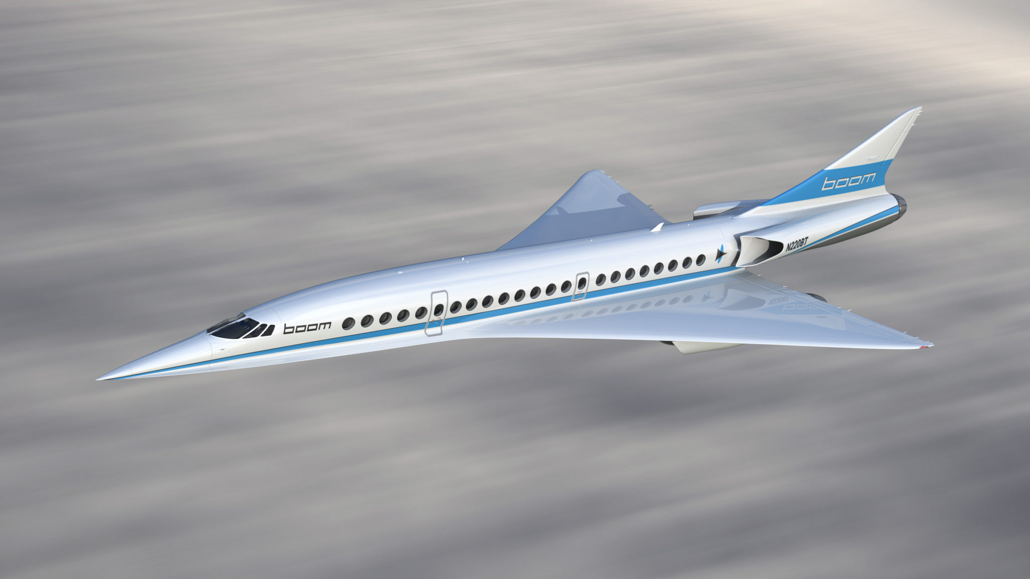
Figure 1. Boom Technologies Boom Mach 2.2 45 seat airliner. Source: Boom.
We based these around a military core with the right characteristics for a low-to-medium bypass SST engine. The fourth engine is a custom-designed straight turbojet, very similar to the engine that propelled the only operational SST, the Concorde.
We will use the reference turbojet to understand the difference to a turbofan in this application and why the selection of an engine for a SST follows different rules than for a normal airliner.
Summary:
- Supersonic flight requires engines with low frontal areas and low mass flows.
- Should the engine be designed as for a normal airliner, the inlet drag would be prohibitive.
- The engine also must have a low pressure ratio core; otherwise the energy of the fuel is wasted on non-productive work.
Discussion
Engine’s design points
The most important phase for an airliner is the cruise phase. This is where the aircraft is spending 90% of the time and 90%-95% of the fuel. For an SST, passing the sound barrier during climb to the cruise altitude is also important, as is take-off and landing.
We will focus this article on the cruise. There is quite a bit to consider for an SST engine to be efficient at M2.0/FL550 or higher. In our final article, we will look at the take-off and climb phases as well.
Cruise at 16,000m
As described in the last article, an SST needs to cruise at a very high altitude. The skin friction part of the drag is simply too high in denser air. Flying at a high cruising altitude also brings down the temperature of the aircraft skin to an acceptable level (around 130°C for the hottest areas at M2.0). The high speed keeps the induced drag low despite a very low aspect ratio (1.5).
At 16,700m (Flight Level 550), the air density is down to 12% of the ground value (0.15kg/m3). We established in Part 3 that we need 5.7klbf of thrust per engine at M2.2 and FL550. An engine based on the EJ200 core produces around 2,500-3,500klbf at that altitude and speed, Figure 2. The table contains our engine candidates with the By-Pass Ratio (BPR) 0.4 engine included for reference. It represents taking the EJ200 Eurofighter Typhoon engine as it is without its afterburner.

Figure 2. SST engine alternatives with key data. Source: Leeham Co simulation with GasTurb.
Should we reduce the speed to M2.0, we would still need 5,200klbf, considerably more than our by-pass engines can deliver. At lower speed or altitude, we don’t gain much. The engines based on a core which is fine for take-off and climb is simply too small for the M2 cruise. How can that be? The data in Figure 2 tells the story.
The engines in the table are all modeled with the help of GasTurb, a professional gas turbine engine modeling tool which is also used by engine OEMs for exploratory work. GasTurb allows us to accurately model the different engines and adapt them for supersonic flight.
The tool also allows us to do a first design of the engine (once we have designed the turbo-machinery for the engine) with dimensions and engine mass, Figure 3. With the availability of this data, we can look at all aspects of the engine, from thrust and fuel burn, to the corresponding engine size and weight.
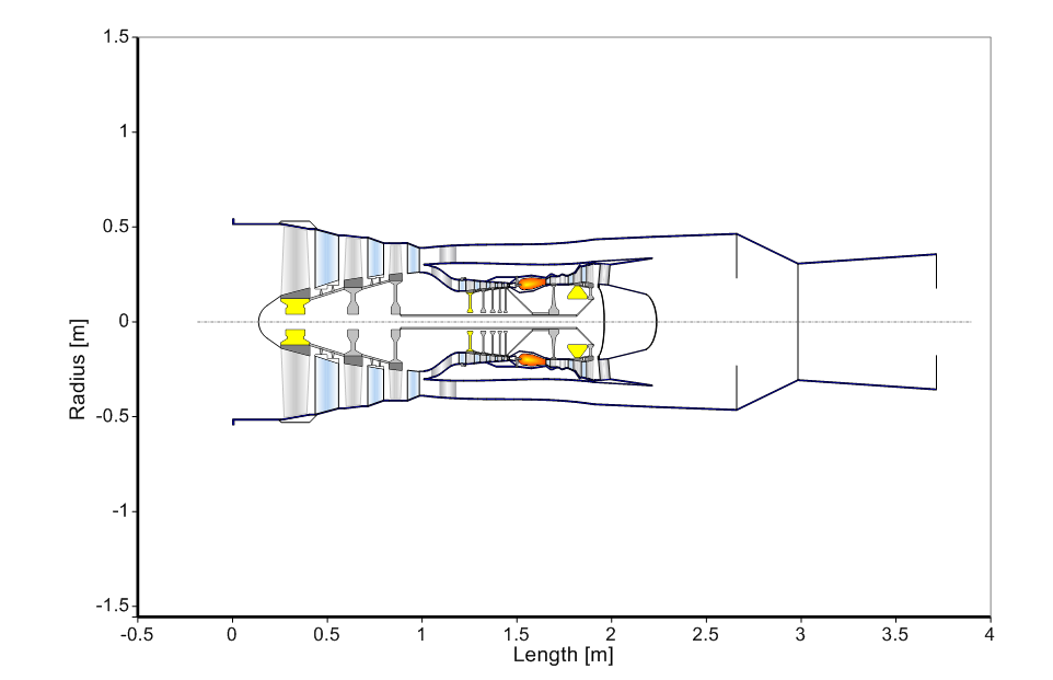
Figure 3. SST engine candidate with BPR 2.0 modeled in GasTurb. Source: Leeham Co.
The engines have been modeled to a level where their main characteristics are settled. To optimize them to the last percent of thrust and fuel consumption is outside the scope of this article series. Such work must include the design of a suitable nacelle with intake and nozzle and must be done in cooperation with the airframe team.
The SST engine candidates compared
To get to an engine that can generate our cruise thrust at M2.2/FL550 (5.7klbf), we need to go to a Turbojet with a mass flow of 150lb/s and a take-off thrust (Sea Level static thrust) of 25,000lbf. This is more than the 18klbf that we defined we needed in article 3. Why?
The BPR2.0 engine we modeled based on the EJ200 core can generate the take-off thrust and is fine for the climb. Why does it fall short on the supersonic cruise?
The reasons are two-fold: RAM drag and too much air to compress.
The primary problem is the inlet momentum RAM drag. An SST is travelling with 650m/s forward speed at M2.2. Its engine is swallowing the air needed to generate the thrust via the engine’s intake. This air must be accelerated to the engine forward speed (650m/s) minus the air speed it has when entering the fan (150m/s).
This means the mass of air entering the engine must be accelerated to 400m/s forward speed. This costs energy, the energy consumed by the inlet momentum (RAM) drag. At M0.8, an engine the size of our largest engine, the BPR2.0 engine, would have a RAM drag of 3,500klbf. At M2.0, this has grown to 7,700lbf. The engine must produce a gross thrust of 11,000lbf to generate a 3,300lbf net thrust for the SST cruise.
The RAM drag hurts engines with large mass flows, like high-bypass engines. Our turbojet, despite having almost twice the thrust at M2.0, consumes less air than all other engines. It achieves the thrust via giving the lower mass flow a large over-speed (specific thrust) of 630m/s, compared to 250m/s for our BPR2.0 engine.
Its RAM drag is low and as it has smaller diameter/weight, its installation drag is also lower. Supersonic flight is especially sensitive to frontal area for all items on the aircraft. The 1.5m diameter for a BPR 2.0 engine is difficult to accommodate in a low wave drag SST.
Fuel burn
The turbojet has a 14% higher specific fuel consumption (TSFC) than the EJ200 reference engine (the BPR 0.4 one) and 40% higher than the BPR 1.0/2.0 engines. Overall the TSFC for all engines at M2.0 is much higher than one would expect. For modern airliners flying at M0.8, we talk about 0.55-0.65 lb per lbf and hour, here we are at 1.2 to 1.6 levels.
The reason is the engine has to work hard at M2.0. The first problem is the RAM drag; the second the high inlet temperature. Compression of air gets harder the higher the temperature is of the air entering the compressor.
Figure 4 show how much harder the doubling of the pressure ratio is after the SST M2.0 inlet (the 10:1 compression gives an inlet temp. of 153°C). Compare it to the work for an inlet temperature of a normal airliner (-25°C at FL370/M0.8). The engine’s compressor has to do 70% more work to double the pressure from 153°C than from -25°C. The comparison is made at sea level pressure (101kPa) but will turn out the same at other altitudes, the difference remains 70%.
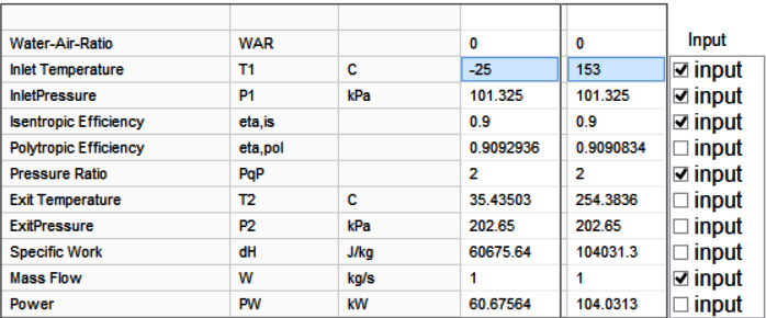
Figure 4. Compression work from different starting temperatures. Source: GasTurb.
This is why SST engines are not designed with high pressure ratios. The intake gives a pressure ratio of 10 (if well designed). Then there is only another 15 times compression left to do in the engine before one hits the max allowed temperature at the end of the compressor.
Between three to five times compression has to be done in the fan section for a bypass engine, otherwise mixing the bypass/core air before entering the nozzle will not be efficient. This leaves a high pressure compressor which has a low compression ratio. Otherwise, this compressor (and its turbine) works outside its design range, i.e., with low efficiency.
Part of the design work for an SST engine is determining the Fan/LPC section’s compression ratios (into the core and the by-pass). Figure 5 shows the type of parametric trade studies that were done for the candidate engines.

Figure 4. Determining the design Fan/LPC pressure ratios for an SST engine. Source: GasTurb modeling by Leeham Co.
Bypass engine sizing
We have refrained from sizing a suitable bypass engine for the Boom SST after our EJ200 core turned out to be too small. This would require finding a suitable core which is larger than the EJ200, yet still small enough to give an engine of acceptable size.
This work cannot be done in isolation from sizing of the airframe. It’s an elaborate iteration engine/nacelle/aircraft where the drag levels of the actual installation of a larger/heavier engine must be traded for more thrust and a changed TSFC.
A straight jet might be optimal for the cruise at M2/FL550 or beyond. But it is not a possible engine for a modern SST due noise restrictions at take-off and landing. It also has a high fuel consumption for all phases of flight. A variable cycle (i.e. variable by-pass) engine would be ideal but this is not compatible with finding an existing core to base the engine on. Experiments have only begun with variable cycle military engines and it’s not mature technology.
Interaction aircraft/engine
The problem is not only an engine problem. A larger engine requires a larger aircraft and we have already high drag levels at M2.2 cruise. A solution involves tuning the aircraft for lower drag (e.g. less wetted area or more slender design).
We have checked our aircraft models drag levels with those from Concorde. We have modeled M2 drag which is about 25% lower than an equal size Concorde would have. One of the reasons is that it’s almost impossible to model the drag around the engine nacelles with their inlets. We have therefore refrained from estimating the wave based interference drag for this area.
We are thus confident that we have not overestimated the amount of thrust needed to propel an aircraft like the SST we showed in our drawings. Finding a suitable engine for a Boom SST can only be done in a joint project, interactively adjusting the airframe and engine for a fit.
What our article series has shown is that it’s hard to define an engine without resorting to a clean sheet design. The requirements are so different to our normal airliner engine.
In our final article, we will summarize the results so far and go through the other factors (like take-off/landing and climb) that must be considered to find an engine solution for an aircraft like the Boom SST.
Hello Bjorn,
French military engines are famous for having comparatively low BPR
Ie :
– M88 (9t AB class with suitable enlarge inlet) is 0.3 and available
– M53 out of production but still in service is also a little lower BRP 0.36 and already M2.2 class
Can it change something ?
Can a 4 engines EJ200 based do the job?
Best regards
The M88 is a bit smaller than the EJ200 so would not help but your idea of four engines is on the right track. I will cover that in the last article, the three engine configuration of the Boom SST can seem OK at first glance but I think there are major problems with it that I will write about in the final article.
All right
Did you know that the M-53 has a variable section in the by pass section ?
It won’t change the analysis i guess
https://www.google.fr/url?sa=t&rct=j&q=&esrc=s&source=web&cd=2&cad=rja&uact=8&ved=0ahUKEwjB7ITgovbQAhWF1BoKHVzMAXcQFggiMAE&url=http%3A%2F%2Fwww.defense.gouv.fr%2Fcontent%2Fdownload%2F399415%2F6008608%2Ffile%2FT%25C3%25A9l%25C3%25A9charger%2520le%2520rapport%2520public%2520BEAD-air-A-2010-008-A.pdf&usg=AFQjCNEt17a4m6evkoAAxL7SXmm2BTLUOA&sig2=1AJYD6neRk3Qv4u-RcV6KA
The variable pypass ratio is interesting. But the M-53 does not have more thrust than the EJ200 and weighs 50% more with a larger diameter. It does not solve our problem of thrust at 50kft and M2.