Leeham News and Analysis
There's more to real news than a news release.


Bjorn’s Corner: Aircraft drag reduction, Part 15

By Bjorn Fehrm
February 2, 2018, ©. Leeham Co: In the last Corner, we discussed the basics of supersonic flow, to prepare for a supersonic and transonic drag discussion.
We will continue the supersonic aerodynamics discussion, however, as there are some further areas needing an explanation before we move on.
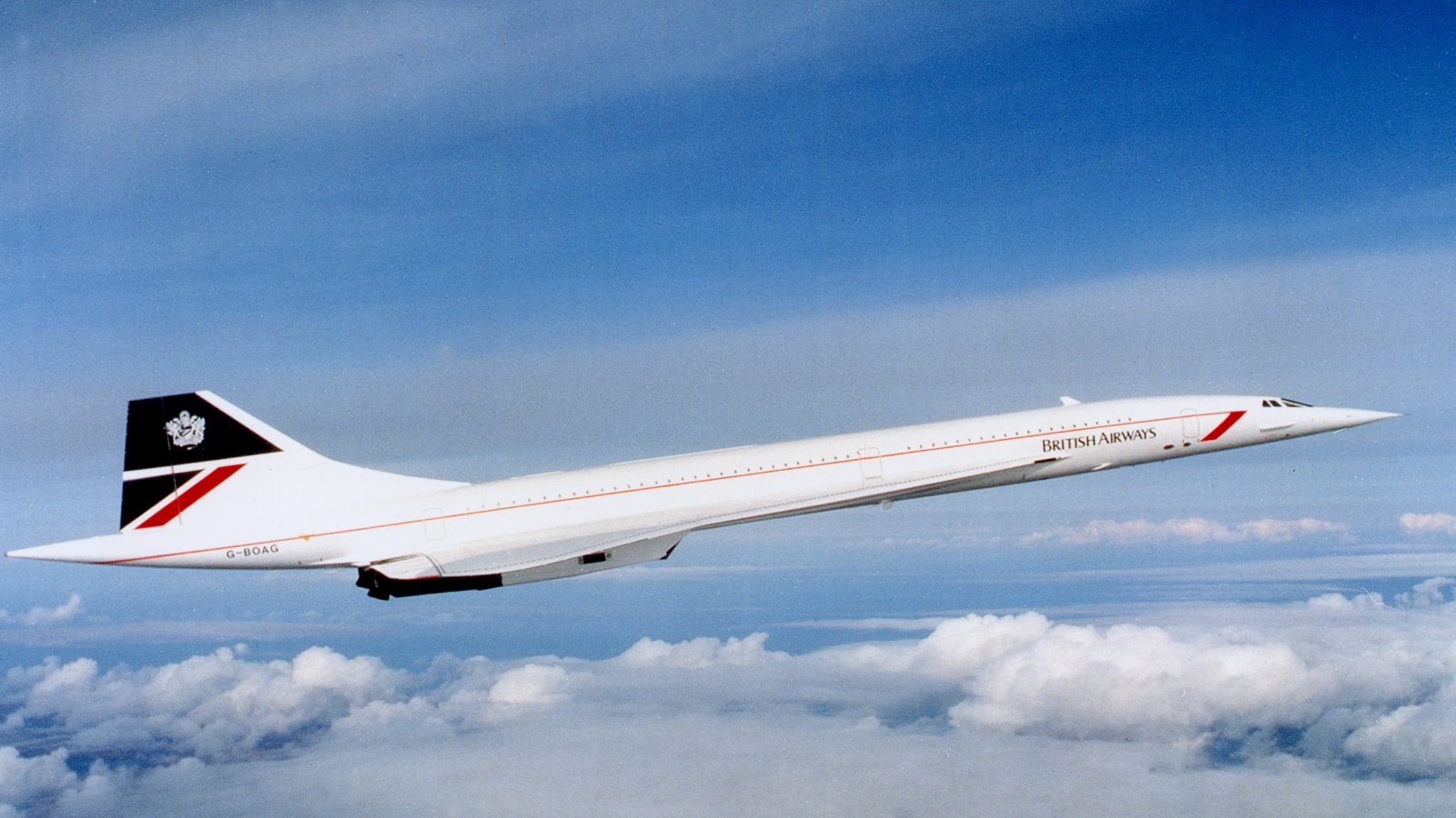
Figure 1. The first supersonic airliner, the Concorde. Source: Google images.
Supersonic flow
In the last Corner, I characterized what happens when the airflow passes through a supersonic shock wave. What I didn’t describe is an additional supersonic flow phenomenon called supersonic expansion fans. These occur when the air flows over a convex shape like the first part of an airliner wing with transonic flow over the top (Figure 3).
Luckily, a kind reader mailed me about this after last week’s Corner. So, let’s get a more complete picture around supersonic flow and what the primary phenomenons are and how these affect airplane flight before we move to the drag part.
Supersonic flow effects
There are two types of supersonic shock waves, oblique (or slanted) and normal shocks. These have slightly different characteristics. We start with the oblique shock.
The oblique shock is created when the flow is compressed by a sharp object or a concave area on the aeroplane. Figure 2 shows the shock which is created by a T38 jet trainer’s nose when flying supersonic (taken in a wind tunnel with special photo techniques).

Figure 2. The nose of a T38 jet trainer flying supersonically has created an oblique shock. Source: Wikipedia.
The oblique shock normally results in a slightly slower supersonic flow behind the shock (in special cases the flow behind the oblique shock can transfer to subsonic flow). Flow density, pressure and temperature increases past the shock (we talk the normal static values here), the Mach number decreases (but stays supersonic in the normal case) and the flow changes direction away from the object after the shock.
A normal shock, like the end shock of the supersonic flow in our transonic wing from the last Corner (Figure 3), has the flow passing from supersonic to subsonic flow. Like for the oblique shock, the static density, pressure and temperature increase across the shock.
Figure 3. Transonic flow around a wing. Source: Wikipedia.
What I didn’t describe last time is that there is a third way the supersonic flow can change state when flowing around an object. If the flow passes a convex surface, like the first part of the top surface of the wing in Figure 3, it will change state through expansion fans (not shown in the figure, but the fans are inside the supersonic flow area).
Across an expansion fan the Mach number increases, the static density, pressure and temperature decreases. On the transonic wing in Figure 3, the pressure decreases in the area before the normal shock and lift is produced.
Use of shocks in supersonic aviation
The supersonic shocks are used in aviation to condition the airflow during supersonic flight. Supersonic airliners (SSTs) are hot right now. We will cover the most worthwhile case of shock use for such aircraft. It’s for the engine inlets.
Turbojet and turbofan engines can’t work with supersonic inlet air hitting the fan or compressors. The ideal condition is air with ~M0.5 passing into the engine.
As we have seen, shocks slow the speed of air while increasing the static pressure. So, shocks can be used to condition the engine inlet air for an SST.
The normal straight or pitot inlet is blunt and therefore creates a normal shock. This takes the flow from supersonic to subsonic speed while increasing the pressure, as we want. But it’s a strong shock and we lose energy in the flow passing the shock. The pressure recovery in a normal shock inlet suffers as the shocks initial speed increases, Figure 4. The normal shock inlet is inefficient for high supersonic speeds.

Figure 4. Intake losses for multi-shock inlets like F15/Concorde/Su27 and std. pitot intakes like F16 or Aerion biz. jet. Source: Cumpsty “Jet Propulsion”.
For aircraft flying above M1.5, a multi-shock inlet gives less pressure losse in the intake. Figure 5 shows the increasing static pressure and slowing Mach in a multi-shock inlet.
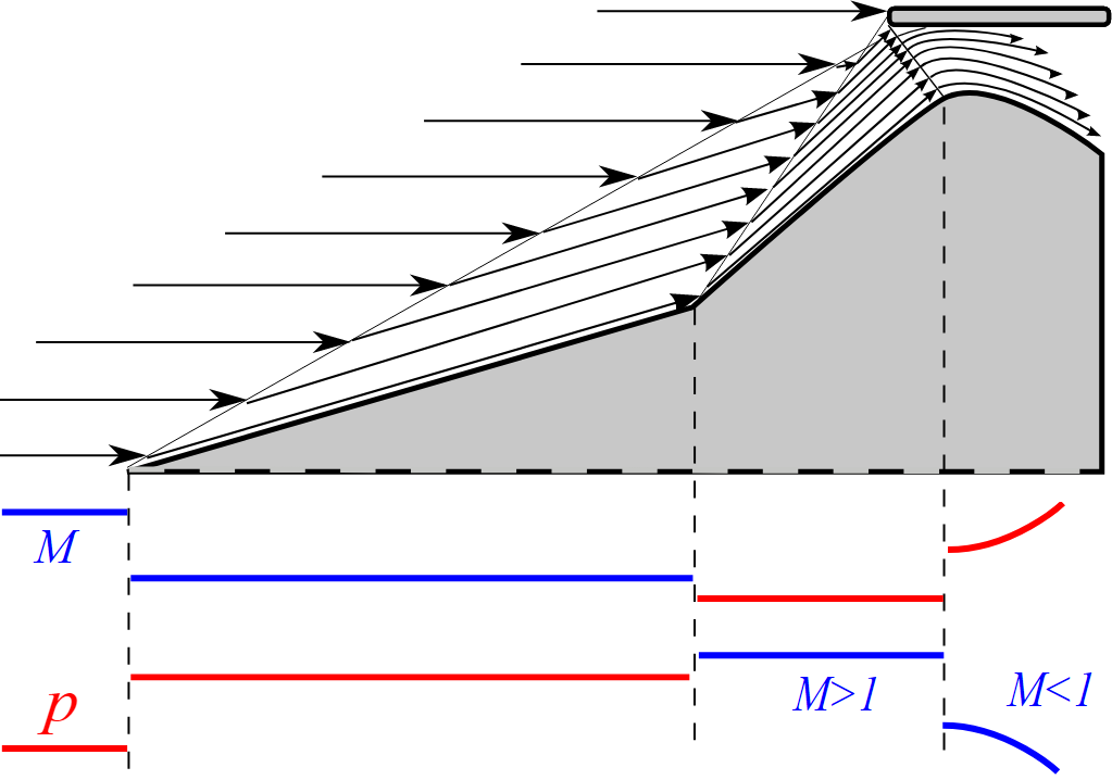
Figure 5. Mach and static pressure p in a multi-shock inlet. Source: Wikimedia Commons.
Observe the direction change of the flow through the oblique shocks. This is used in the F35 “bump inlet” or SDI (Supersonic Diverterless Inlet) to direct the boundary layer around the ends of the intake lips.
The Concorde inlet (Figure 6) uses four weaker oblique shocks to slow the air down, giving an intake pressure recover like the F15 curve in Figure 4.
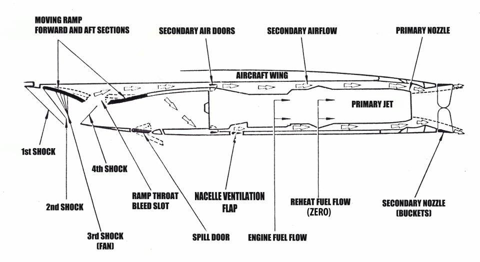
Figure 6. Nacelle with variable inlet and exhaust for the Concorde. Source: Google images.
The shocks in a multi-shock inlet must be managed to direct the flow after the shock in the right direction and to keep the shocks weak. Therefore, advanced supersonic inlets have variable shock creating areas. Like the movable ramps used for the Concorde, F15, Su27, Typhoon inlets or the cone shock areas used for Mirage, Mig21 or SR71, Figure 7.

Figure 7. Multi-shock inlet cone for late model Mig21. The aircraft’s radar is housed in the movable inlet cone. Source: Wikipedia.
Hi Bjorn,
When did this stuff you are describing stopped being state secret/classified information and become public knowledge we teach in schools. It must have been a cutting edge in early cold war competition.
Before the advent of computational fluid dynamics that could handle transonic flow conditions, Boeing had a decided advantage. Boeing built a transonic wind tunnel (BTWT) and used it to develop the B-47 in the late 1940’s.
This dedicated Boeing facility made possible the “cut and try” aerodynamic development process common be digital analysis was possible.
All Boeing jet transports have begun their lives in the BTWT.
Thanks Bob,
got done right after NASA cracked the slotting of the measurement section then to get transonic tunnels to work.
Agreed.
Hi Kamil,
the very long history of discovering the effects of supersonic flow is a story in itself. Prantdl and others before his team developed the theories of what would happen once you are supersonic and gun ballistic experts had dealt with supersonic bullet flow for centuries (this was why the first supersonic test aircraft, the Bell X-1, had a bullet-shaped fuselage). Wind tunnels for supersonic flow (above M1.2) have been available for 100 years.
The tough part was the transonic flow region, M0.9-1.2, where you have a mix of subsonic and supersonic flow on the aircraft. It took until after WW2 to get transonic tunnels to work and the full prediction of transonic effects without tunnel tests only got cracked when modern transonic CFD was possible in the last three to four decades (because of the immense computing power needed for the iterative solution methods).
NASA publicized some important reports re. supersonic flow 1951, so there was some open literature but a lot was classified. The knowledge how to make supersonic inlets came at the time. The 1960 Mirage III, Mig21, and Phantom F4 all had movable supersonic multi-shock inlets.
NACA/NASA was not available to the French.
Strong influx from German researchers going to France and the UK, US.
( and the US and especially Boeing got itself a leg up via Operation Paperclip.)
Lots of post war research was not creative but more applicative.
Thanks Bjorn, always interesting.
On the drag for airliner engines, seems for a novice not much has changed for many years in nacelle design. What contribution (X?) does drag on say a 787 or 350 have on overall fuel burn?
The drag from the engine and nacelle is divided into two parts:
– the engine drag depends on the engine thrust position. Engine caused drag is normally included in the engine thrust and fuel consumption figures. At high throttle settings, the drag is small. At flight idle, the intake will spill air and the engine thrust (which includes drag) will actually be negative dependent on speed. But this is all covered in the engine thrust.
– The nacelle in itself has wetted area drag based on its size and any form drag from separations. The pylon can also have interference drag (we come to what that is). Total nacelle+pylon drag is about 3-4% of total aircraft drag for modern high-bypass engines.
Thanks Bjorn, really interesting. I am in mining very different, think it must be great “living” in a wind tunnel and see the results of your ideas.
Hello Bjorn,
Thanks as ever for another very interesting article!
One thing I’d heard about supersonic inlets was that sloped rectangular inlets (Tornado, B1B, F15, etc) tended to be easier to design so as to keep the airflow to be stable despite disturbances caused by, for example, manoeuvring (whilst still being efficient). Whereas as highly tune circular spike inlets (e.g. SR71) are more prone to upset (causing the infamous head-jarring SR71 un-starts).
Is any of that basically right?
Hi Matthew,
I would think so. Rectangular inlets have become more common as manoeuvre requirements have increased, ref. Mig21 and Su9 vs. Mig29 and Su27/35. You seldom see cone or half cone multi-shock inlets today on fighters, probably because the vertical ramp inlets works better over the complete flight envelope.