Leeham News and Analysis
There's more to real news than a news release.

Bjorn’s Corner: Supersonic transport revival, Part 11
October 19, 2018, ©. Leeham News: In the last Corner we discussed the temperature challenges an SST engine faces.
Now we address an even larger problem for SST engines, the takeoff and landing noise.
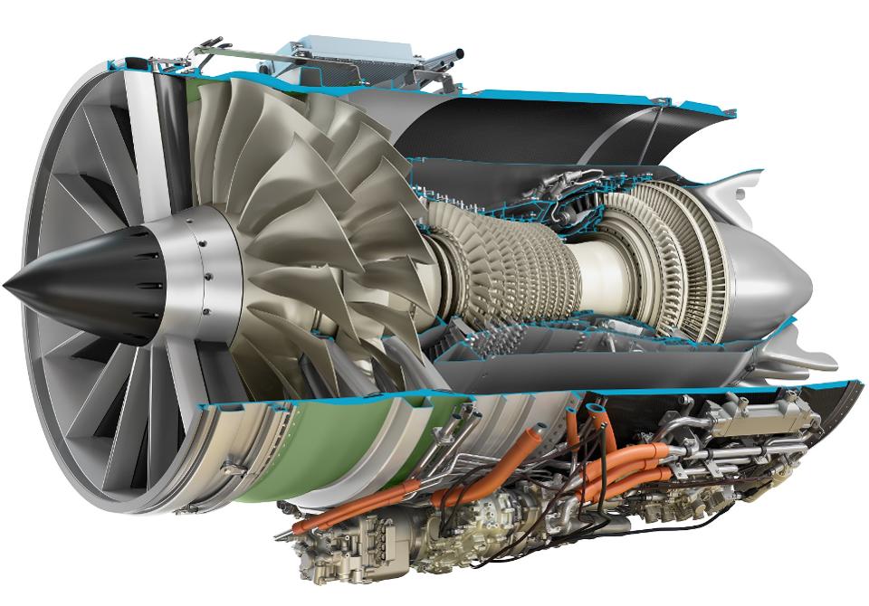
Figure 1. The GE Affinity SST Turbofan for Aerion AS2. Source: GE Aviation.
The noise challenge
A jet or turbofan engine have two noise sources. The exhaust and the intake areas.
The intake noise comes from the fan’s fan blades. At takeoff thrust fan RPM the fan blades’ tips rotate with supersonic speed. This creates shock waves and it’s these shock waves we hear as a see-saw sound when an airliner start the takeoff.
The inlet sound is dampened by perforating the inlets and putting dampening materials in the cavity behind the perforations, like an exhaust silencer for a car. The inlet sound is not the main problem for an SST engine. It’s the exhaust sound.
Exhaust sound and the engine’s specific thrust
One talk about high bypass ratio engines as being the way to a low noise. It’s not the bypass ratio in itself which gives the low noise, it’s the resulting lower overspeed of the air out the back to produce a certain thrust level. The engine speak name for the overspeed is specific thrust.
An engine’s thrust has two components, airflow and specific thrust (the overspeed of the airflow out the back relative to the aircraft). If we increase the airflow we decrease the specific thrust for the same thrust level.
The noise from the back of the engine is created when the jet from the engine hits surrounding air. This creates strong turbulence which creates pressure waves = sound. The faster the jet, the stronger the turbulence and by it the sound.
This sound has a lower frequency than the intake sound. It, therefore, travels longer and propagates around objects easier (dampening or sound walls are less effective).
The way to dampen this sound from an engine is to lower the specific thrust. Modern engines like the Pratt & Whitney GTF and CFM Leap have a specific thrust below 300m/s for their highest thrust variants at takeoff thrust.
Yesterday’s medium bypass turbofans had a specific thrust of 400m/s or more and Concorde’s specific thrust at takeoff was 900m/s.
Low specific thrust doesn’t fit SST engines
If we lower the specific thrust to lower noise we must increase the engine’s airflow to keep the same thrust level. But we have seen increased airflow increases Ram drag (SST Corner 7).
A heavier chunk of air must be accelerated to within 0.5 Mach of the aircraft speed, then braked to zero and accelerated in the other direction to produced thrust (all relative to surrounding air. We observe an air molecule traveling through the engine).
The increase in airflow is done by increasing the bypass of air around the core. A higher bypass ratio increases the diameter of the engine for the same thrust. At high speed, a low specific thrust engine needs to increase the airflow to the level where the engine diameter creates high volume wave drag (SST Corner 2). The engine weight increases as well.
GE has made a clever move for the Affinity engine for Aerion’s AS2 (Figure 1). The engine has a static full throttle specific thrust of around 500m/s but this thrust level is not needed for takeoff. The engine’s maximum thrust is needed when the AS2 shall pass the sound barrier at 40,000ft.
At takeoff, the engine is throttled to a specific thrust of around 350m/s, as more thrust is not needed. By it, the AS2 can comply with the more rigorous Stage 5 takeoff and landing noise regulations which comes in effect by 2020.
In the next Corner, we will look at key data for different engines for SSTs. We will examine engines with different specific thrust levels and look at how Ram drag versus Net thrust varies as we vary speed and what happens with engine diameters and engine weight.
Assuming that Affinity is indeed a derivative engine with a CFM56 Core, it is hard not to observe the “waste of Power” for the Aerion.
While with 2xCFM56 we can transport 200+ passengers at M0.84, the Aerion is intending to transport 12 (!?) passengers at M1.4 with… 3xCFM56?
Something is fishy here, don’t you think so?
Hi Ferenc,
we need to think a bit differently for the profile of an SST. Takeoff is no longer the toughest part of the flight envelope, passing the sound barrier is. This is where these three CFM56 cores do their maximum job, cruising at M0.9 or 1.4 they throttle back and consume less fuel as for takeoff as well. The AS2’s climb performance will be interesting.
I guess at the takeoff with OEI the AS2 can tap into the full power of the other two engines via a large APR. The few instances the AS2 will lose an engine at takeoff I think FAA/EASA would accept noise above Stage 5.
Not to mention the relative waste of CAPEX and OPEX. The idea that any of these proposals will come in at business class fares (or less) is fanciful, at best.
Ferenc:
I like the tech aspect as its interesting.
Like a lot of things in this world (US 2 trillion tax cut for wealthy) its not about most of us, its about the elite.
I don’t support it either, but I am not driving the train, or to put it another way, no one cares what I think.
It has occurred to me that with modern communication and the rapidity, we could move to a more democratic system as we could all vote.
Legislatures would just become proposers.
It wold make for a more interesting balance me thinks.
Hello Arguendo,
Regarding: “The idea that any of these proposals will come in at business class fares (or less) is fanciful, at best.”
I think that for a 12 seat SST, the relevant comparison prices would be charter rates for a top of the line currently available 12 seat executive jet, i.e. around $10,000 per hour, not business class fares for scheduled flights.
Some total charter cost examples from the following link.
New York to London, 9 to 19 passenger jet: $100,000.
Only $10,000 per person if you fill 10 seats! For comparison, Delta’s one way fares are $6,543 to $7,206 for Delta One lie flat seats on non-stop Delta flights tomorrow 10-20-18 from JFK to Heathrow. If you are travelling with 15 or more friends or co-workers, the executive jet charter might actually be cheaper than a 15 or more last minute tickets for lie flat seats on a scheduled flight, since $100,000 / 16 = $6,250 per person.
Los Angeles to Hong Kong, 9 to 19 passenger jet: $345,000.
https://www.claylacy.com/jet-charters/charter-costs/
When you look at the speed triangel of blade top speed and the inlet air speed ( in an Engine coordinate system) making 2 legs of the triangle you get high blade tip speeds, one trick is to curve the blade tip so the speed normal to the blade tip l.e. comes down and hence reduce the shocks. Just look at the GE90 blade at MOMA, https://www.moma.org/collection/works/93637
@bjorn, WRT the specific thrust vs noise issue, I assume using variable fan outlet ducting it would be possible to have a fan optimized for 500-800m/s overspeed with an optimum duct but at takeoff, some access doors/vanes open to a “third” duct (turbine, cruise fan and takeoff aux fan) duct, effectively increasing the fan exit duct volume and thereby slowing the fan exit speed? wouldn’t do anything to reduce fan noise from the small diameter high speed fan, but would reduce the exit velocity and low frequency noise…
is this the “variable cycle” magic that has been talked about so much for the next gen of US fighter engines?
Hi Bilbo,
yes it is. A variable cycle engine uses duct valves to vary the bypass ratio and specific thrust of the engine between low speed and high speed operation. It has turned out to be challenging to make such an engine.
3 CFM56 derivatives to power the aircraft creates confidence and enables to bypass some stringent ETOPS requirements.
Good point
ETOPS doesn’t apply to 3 engine jets, or buJets. only 2 engine paxJets
Hello bilbo,
Regarding: “ETOPS doesn’t apply to 3 engine jets, or buJets. only 2 engine paxJets”
As of 2007, in the US, according to the FAA, ETOPS stands for “ExTended OPerationS” instead of “ExTended Range OPeration with Two Engine AirplaneS”, and does apply both to airplanes with more than two engines, and Part 135 air charter operations, i.e., companies in the business of chartering aircraft to customers who are not full or partial owners of the chartered aircraft.
Below is an excerpt from a relevant January 2007 FAA advisory circular, which may be found at the link after the excerpt.
“Formerly the term ETOPS signified “Extended Range Operation with Two-Engine Airplanes.” ETOPS guidance has been used for over twenty years to allow two-engine airplanes in part 121 operations to deviate from the regulation that limited the distance these airplanes could fly from potential diversion airfields. With over twenty years of successful experience in ETOPS operations, improvements in aircraft technology and reliability, and the prospect of airline operations on routes of increasing distance and remoteness, the FAA and industry agreed that ETOPS guidance should be reviewed, evaluated for potential application to all airplanes, and codified in the regulations. Note that the changes can be characterized by the change in meaning of ETOPS to “Extended Operations” since these provisions have broadened to include aircraft with more than two engines and to include both part 121 and part 135 operations.”
https://www.faa.gov/other_visit/aviation_industry/airline_operators/airline_safety/info/all_infos/media/2007/inFO07004.pdf
Here is how Boeing summarized these new ETOPS rules in a 2007 issue of their Aero magazine.
“For the first time, this new rule also applies ETOPS enhancements and protections to the extended operation of three- and four-engine passenger airplanes. For these “tris and quads,” ETOPS applies when the airplane flies beyond 180 minutes of an adequate airport. To ease the transition to the new rule for all current operators, delayed compliance dates are specified for many of this rule’s requirements.”
“Although the new ETOPS rule embraces airplane design, maintenance, and operation, this article focuses primarily on the rule’s operational impacts. Moreover, the discussion is confined to flights conducted under U.S. Code of Federal Regulations 14 CFR Part 121 (scheduled air carrier operations), even though the new rule for the first time also applies ETOPS to flights conducted under 14 CFR Part 135 (commuter and on-demand operations).”
https://www.boeing.com/commercial/aeromagazine/articles/qtr_2_07/article_02_1.html
“Revised regulation 14 CFR 121.161 codifies ETOPS and provides updated requirements for the authorization of extended operations. For twinjets, ETOPS applies when the airplane is more than 60 minutes from an airport. For three- and four-engine passenger airplanes, it applies when the airplane is more than 180 minutes from an airport.”
https://www.boeing.com/commercial/aeromagazine/articles/qtr_2_07/article_02_7.html
I stand corrected.
still don’t think it matters for this aircraft given the 180 minute threshold, transatlantic mission profile and speed.
the aircraft is unlikely to ever be more than 180 minutes from gander, bahamas, keflavik or shannon
– A low specific thrust creates high volume wave drag.
– A low specific thrust creates less pressure waves, e.g. sound (takeoff).
– Low specific thrust doesn’t fit SST engines.
– Aerion SS2 SST engines have quite a low specific thrust (350 m/s) during takeoff.
Your analysis isn’t very exhaustive.
What facts/perspectives are your intention to convey?
Hi Mattias,
The ideal turbofan engine cycle for low speed is a low specific thrust engine which has a high mass flow. This gives the required thrust at high propulsive efficiency and low noise. Ram drag is not a dominant problem at these speeds.
The ideal turbofan engine cycle for high speed (Mach>1.5) is a high specific thrust engine which has a low mass flow. This gives the required thrust at lower propulsive efficiency but the lower Ram drag more than compensates for this. Ram drag is the dominant problem at these speeds and the low mass flow curbs the Ram drag. It leads to a higher overall engine efficiency. Engine noise is not a factor at 50,000ft.
The problem is how to handle takeoff and landing at low speed and the regulated low noise levels and still have acceptable high-speed efficiency? GE Aviation throttles back an engine with a specific thrust adapted to Mach 1.4 cruise to get the needed specific thrust for takeoff and landing noise regulations.
The ideal engine for SSTs is a variable cycle engine. These use valves in the engine to get low specific thrust and high mass flow at low speed. As you accelerate to high speed the valves change the path through the engine to less mass flow and higher specific thrust for the need thrust and efficiency at these speeds. Such engines are in a research stage right now and they make slow progress.
I wonder if this program won’t be taken over by Gulfstream, BBD or Dassault at some point. It seems hard to fully implement if there no strong existing support infrastructure.
Why would they introduce a new product that undercuts their own existing very high end business jets ?
The name you should have said would be Cessna?
Gulfstream and Dassault have their own proposals. But all required a new engine of GE Affinity style. GE with the massive CFM56 core production capability can make them pretty cheap. The US military most likely see applications for this engine family and has given a thumbs up to GE (like a new supersonic JSTARS- AWAC), so the “Genie is out of the bottle” and the US will adjust speed limit over land to noice limits giving US Aircraft with US engines pole position. for commercial sales.
JSTARS/AWACS as manned platforms are going the way of the dodo.
supersonic speed is also not interesting for their mission profile, long endurance and high electrical capacity is.
more interesting is tailored low observables and low probability of intercept radar and commo systems.
We will see what Pentagon and Dayton will decide. Being able to get out of trouble at M1.6 in a stealth Aircraft with shut down radars can feel good while enemy fighters with lit A/B’s chase you and pretty quickly run out of fuel.
Wasn’t the F101 from GE, used in the original B1 bomber the basis for the civil CFM56, which would mean in practice the core comprising the compressor, combustor and HP turbine. Deja vue all over again as they say
What surprises me is the 2 stage fan. I was always led to believe 2 stage fans (C5) make a lot more noise than 1 stage. If a 2 stage fan works here why not on next gen LeapX?
I also find the economics of the AS2 interesting but dubious. A third more fuel for a third less range and passenger capacity. Is a 2 hour times savings NYC to London worth the double (or more) operating costs ?
Possible for organizations far richer than mine … But how many units could be sold with those economics.
Bravo for private organizations to push the envelope here, I hope they succeed, but I fear they will not.
The number of fan stages goes with the needed specific thrust, i.e. the overspeed you need out the back. On the LEAP and all other civil airliner engines, you get the wanted low specific thrust with a one stage fan where the pressure ratio is between 1.4 to 1.8 when standing still (static pressure ratio). For an SST engine, you need a higher pressure ratio down the bypass duct to match the core exhaust pressure and get your higher specific thrust. Thus you need two fan stages for the Mach 1.4 optimized Affinity and a Mach 2.2 engine probably need three stages for an even higher pressure ratio.
Is that just a part of the cut-away or is there a bypass duct wrapped around the engine ? It seems to take air after the first compressor stages. When this came up with concorde engine, the ‘air duct’ took compressed air from the inlet, but not from the engine stages.
The Affinity is a bypass turbofan so there is a bypass duct after the two fan stages. The outer shell is made of CFRP to lower weight according to GE. The Concorde engine was a straight jet, hence it didn’t have any bypass duct. The nacelle could open valves to let cooling and spill air past the engine which then combined with the engine jet before the divergent nozzle.
Your article is very informative, and some of my guesses seem to agree with your ideas on the Affinity Engine.
One thing that holds my attention is the exhaust mixer, that alot of people assume is there purely for sound suppression. I think it’s more important purpose is homogenizing the bypass and core flows before hitting the translating convergent-divergent “bullet/Zweibel” nozzle that this engine is supposed to have.
Low bypass afterburning turbofans have to use forced mixers to better accomodate the afterburning arrangement but of course have C-D nozzles to deal with exhaust losses when not in afterburner.
Going back to the Affinity’s mixer, what’s the point of having sound suppression when it’s so well contained and in the end is coming out the back through a serated annular plug nozzle?
Without the high exhaust velocity of the core, I don’t think even a dual fan bypass of this caliber (very high RPM?) could deliver fast enough velocity to push this engine to supersonic.
Not to discount the use of dual fans, but I think mixer and nozzle arrangment is a key part of this engine’s abilities.
Hi Blitzvogel, yes the mixer area and the nozzle are very important for a bypass SST engine. See the response to Kant for more background about the mixing shapes and the reason for a dual fan. A single fan would not work for SST engines, it creates to little pressure gain (pressure and air speed are just two sides of the same coin. You trade one for the other through convergent/divergent sections in the engine up to chocking).
Bjorn,
First time I have seen the inside of the GE Affinity engine. Thank you for a nice analysis. Let me point out a few more things.
Shock waves formed due to supersonic flow near the blade tips generate high frequency buzz-saw noise (more correct term). But additional high frequency noise is also radiated forward by the fan and is due to the wakes of rotating fan blades being cut by stationary vanes downstream (to remove the swirl) in conventional separate flow stream turbofans. This noise is radiated backward as well and the noise intensity can be reduced by diffusing the wakes. That is why the stationary blades are located far aft of the fan. They also provide structural support to the fan casing.
Affinity design appears to be different. From what I can see from the cutout, each fan stage has high aspect ratio stationary vanes immediately downstream. This design is likely to produce a higher noise because the wakes of the rotating fan blades are still strong when cut by stationary vanes downstream. Secondly, the engine has inlet guide vanes very similar to military very low BPR engines. Inlet guide vanes are usually avoided in civilian engines because of the strong blade passing frequency noise generated by fan blades cutting the wakes of the inlet guide vanes. So it is an interesting design combining some aspects of a military engine with the core of a civilian engine. Can you comment on the influence of this design on noise radiated both forward and backward?
Interesting to see the core nozzle. Very much similar to noise suppressors used on early Boeing 707 engines to mix the exhaust stream quicker and reduce the jet noise.
Single stage HPT and two-stage LPT driving just the fan. Any idea what the pressure ratios of the 2-stage fan and 9(?)-stage HPC are?
Hi Kant,
thanks for the fan noise additions, I’m not able to add anything to what you put there. Re the fan pressure ratio, it seems it should be around 2.5-2.8 Static to match the bypass exit pressure with the core exit pressure. The mixer area is dependent on equal pressures to work well. The core nozzle is also similar to the latest Bix jet engine design, Passport. It’s a mixed engine and its design has been carried over to the mixer for the Affinity it seems. Engine efficiency is dependent on an effective mixing of the gasses in this area, the shape of the core nozzle helps with the mixing of the gas streams.
The High-pressure compressor is the same as for the CFM56 (I wrongly wrote in a previous corner the CFM56 core has 10 stages, it has nine, the same as the Affinity). As such it has a max. RPM (typically TOC or V2) pressure ratio of around 10. At cruise at Mach 1.4 it’s lower, around 8.5.