Leeham News and Analysis
There's more to real news than a news release.


Bjorn’s Corner: New aircraft technologies. Part 15. Airframe for lower Induced drag

By Bjorn Fehrm
June 1, 2023, ©. Leeham News: Last week, we examined ways to lower the dominant drag of an airliner, the air friction drag (Figure 1).
Now we look at the second largest drag component, the Induced drag, and how it can be reduced. We go through the fundamentals of the drag to understand how to affect it. Then we look at aircraft changes to reduce Induced drag and if these make sense on an overall aircraft efficiency level.
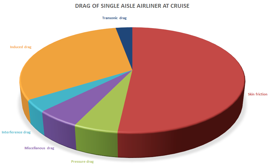
Figure 1. The drag components on a typical single-aisle airliner at cruise. Source: Leeham Co.
Airframe technologies for lower Induced drag
If air friction drag can be called “ drag due to size” of an airplane, the Induced drag is “drag due to weight”. So the first action one can take to reduce Induced drag comes from this simplification, reducing the airplane’s weight.
Weight is the downward force caused by the earth’s gravity pulling on the airframe mass. It’s measured in lb in the Imperial system and Newton in the SI system. Note that lb is often used instead of the correct slug to denote mass in the Imperial system, whereas SI here uses kg. It’s why we use lbf for weight and other forces in our series.
Induced drag comes from the air’s desire to stream from a higher-pressure region below the aircraft’s wing to a lower-pressure region above the wing when flying, Figure 2.
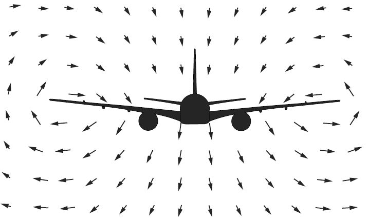
Figure 2. The global movement of air from below the aircraft wing to its top side. Source: Leeham Co.
The forward speed and the air circulation around the wings cause a wide rolling-up wake behind the aircraft, Figure 3. In the image, we can see the air downstream of the aircraft is affected over six wingspans wide.

Figure 3. Image showing the spreading of the Induced drag vortex sheet. Source: Thales.
An aerodynamicist that has described the widespread effects of an aircraft on the surrounding air is Doug McLean in his excellent book “Understanding Aerodynamics.”
McLean debunks several myths in the book. Examples: wingtip devices working by local modification of the airstream; aspect ratio is related to Induced drag, and the Prandtl box wing works beyond an in-the-vertical plane staggered wing.
The Induced drag of aircraft is dependent on the parameters in the Induced drag formula;
Induced drag = Lift^2 divided by 0.5 * Air density * Speed^2 * Pi * Wingspan^2
Let’s look at these relationships and understand what they mean:
- Lift is squared. It means if we double the cruise weight of the aircraft, Induced drag increases four times. We now understand why aircraft designers are crazy about weight and, therefore, mass, hunting it down to the last gram.
- Wingspan is squared. It means if we double the wingspan, Induced drag reduces four times. This is why all battery-based aircraft, which are VERY heavy, have wide-span wings.
- Speed is squared. It means if we double the speed, Induced drag reduces four times. It also means Induced drag is at the maximum at low speed during takeoff and landing, where it constitutes 70%-90% of drag, Figure 4.

Figure 4. Drag components change with speed. Source: Leeham Co.
Figure 4 shows there is an ideal speed for the lowest drag where Induced drag and Parasitic drag (where friction drag dominates) are equal. This is called the green dot speed in an airliner, and it’s the speed at which waiting patterns are flown. As an airline has many costs that increase with time, the cruise speed is higher than the speed of lowest drag.
Low air density increases Induced drag, but it’s not squared. Therefore, airliners fly high as a lower air density reduces air friction drag. An airliner gains in total drag by flying high, as this brings the two drags closer to the center in Figure 4 (Induced drag increases and Parasitic drag decreases).
The Induced drag equation is valid when the lift distribution of the wing is elliptical. As this is seldom the case in practice, an “Oswald’s efficiency factor” e is added to the denominator.
A practical airliner wing seldom has an ideal elliptical lift distribution as mechanical or other aerodynamic constraints deviate the wing from an ideal elliptical lift distribution. Engines on the wings also affect lift distribution, propeller engines in a major way, and jet engines to a lesser degree. With typical e values of 0.8 to 0.9 for modern airliner wings, it increases the Induced drag by 11% to 25%.
We now know we can reduce the Induced drag by:
- Reducing weight
- Increase wing span
- Increase speed
- Design a more ideal wing lift distribution
We will look at aircraft architectures that use these four factors to reduce Induced drag in the next Corners. We will also use our Airliner Performance Model (APM) to calculate the gains from different architectures.
There is another way to reduce induced drag. A downforce is required to maintain equilibrium of the aircraft, countering the pitch down moment from the wing. Generating that force aerodynamically from the horizontal stabilizer effectively adds to the weight of the aircraft (it is reacted by increased lift on the wing) and also adds an induced drag component from the downwards ‘lift’ from the horizontal stabilizer.
Shifting the the c.g. backwards as far as you can – while still maintaining the stability of the aircraft – lessens the aerodynamic downforce required from the horizontal stabilizer and the lift from the wing.
The Airbus A330 pumps fuel from the wing/centre tanks into the horizontal stabilizer in cruise to achieve this – about 4 tonnes I think, so quite significant. I think the 747 might too. There’s already a fuel line leading to the APU and it uses that.
I’m surprised that other aircraft don’t do it – the 767 for instance. There must be a downside because it seems a relatively easy win.
The downside is stability. An aircraft with a CG forward of the centre of pressure will tend to stability, consider encountering turbulence: if the lift suddenly reduces, the moment from the centre of pressure will reduce and the aircraft will pitch up, increasing lift and restoring level flight. Of course, if CG and CP are on top of each other, constant shifting of trim, at times very quickly is needed. Think of seabirds, they have their tail folded in normally because it lets you cut away a large source of drag, but they have to constantly twitch it up and down to maintain level flight.
Adding some parenthesis makes it easier to read: Cdi = (Cl^2) / (pi * AR * e). Cl = Lift coefficient.
The total drag coefficient, Cd is equal to the base drag coefficient at zero lift Cdo plus the induced drag coefficient Cdi.
So the Drag the engine thrust has to equal is D = Cd * A * .5 * r * V^2
r= density, A = reference area, V= speed
So can you reduce time at airport from car parking to T-O you could reduce flight speed for the same arrival time and hence save alot of fuel.
This series is great, thanks a lot!
Agreed.
One strategy to deal with carbon emissions would be to mandate aircraft speed at cruise to its most efficient. Violate that (say to make up time on a behind schedule flight) and it costs you.
As it would be relatively equal, no airline would pay a penalty for cruising at maximum efficient speeds.
ATC and weather are the cause of most/all delays once airborne. And it can work in reverse as favourable weather can mean early arrivals.
More recently Ive heard of long delays after landing – say 30min- waiting for their gate to become free
Duke:
I have not traveled beyond the Western US in the last 20 years, but I never had a delay ever traveling due to ATC or Weather. If we took off in time we were on schedule, if not they have some speed in reserve as they usually make up the time.
Now West of the Mississippi is not crowded other than spot places like SFO, LAX, SEA. Eastern US Seaboard probably more resembles Europe.
But the point is all the talk about more efficient and slowing down would be low hanging fruit. I know there is some as the Anchorage Fairbanks run was 45 minutes when I first flew it in jets and now its an hour.
I cannot wait for the rest of this series!! I’m hoping bell-shaped lift distributions make an appearance…
I always wondered what the impact of curved vs. straight cockpit windows was (f.e. A220 vs. A320), or how it could be calculated.
Normally the geomtery is complicated so you have to use Computational Fluid Dynamics (CFD), for lower speeds wind tunnel testing gives good answers. You not only want to know drag, sound is also important.
A320 was from the late 70s era , so possibly the computing solutions wasnt to such a fine detail. A220 is around 30s years later when it was.
Yes, used to be that fighter jets had a flat front window to protect for bird impact. The A380 has plane cockpit windows but 787, A350 has curved. So there was a technology shift around that time.