Leeham News and Analysis
There's more to real news than a news release.


Bjorn’s Corner: New aircraft technologies. Part 31. Detailed design -3

By Bjorn Fehrm
September 22, 2023, ©. Leeham News: Last week, we discussed program management methods for the Detailed design phase of an airliner development program. While the modern Agile work methods suit smaller projects, the sheer size and complexity of an airliner project that involves hundreds of companies require more structured management methods with Agile used for areas where it’s suitable.
We now go a step deeper than program and configuration management and look at development techniques and tools for Detailed design.
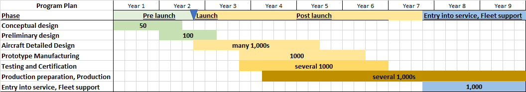
Figure 1. The development plan for a new airliner. Source: Leeham Co.
Tools that enable rational work
In classical airliner development, Preliminary design had its tools for the overall design of the aircraft; Detailed design had its CAD (Computer Aided Design) tools and PDM (Product Data Management) database to store and workflow the results approval process.
The production engineer then took the CAD data from the PDM and prepared the manufacturing with his CAM (Computer Aided Manufacturing) toolset, and entered the Bill Of Material (BOM) and work instructions into the company’s ERP (Enterprise Resource Planning) system. Finally, the training, documentation, spares, and maintenance departments used their documentation tools to create manuals for training and documentation for repair and maintenance.
In the complete chain, a part like an access hatch or landing gear door was remodeled in 3D at least five times (CAD, CAM, Documentation, Spares, Maintenance, possibly also subsupplier CAD and CAM), and its design data passed through five to 11 systems (CAD, PDM, CAM, Production ERP, QA, for subsupplier add Purchase, Subsupplier CAD/PDM/CAM/Production ERP and QA), each time with a slightly different focus and data set.
The above is an obvious inefficiency that the OEMs have been fighting for decades; you should create a 3D dataset only once and use it in all the steps. But in a world of hundreds of legacy and new IT systems to run the company, each replacement of something old and standalone “but that works” with something new, more integrated is a significant effort.
Design automation companies like Dassault have, over the years, built an integrated development and manufacturing toolset (called 3DEXPERIENCE by Dassault) that shall cover most steps in the chain.
But while it’s reasonably straightforward to replace legacy CAD and PDM systems with an integrated suite, it gets harder as we come to production. The production preparation tools in the CAM suite can be replaced, but the outright production is governed by the company’s ERP (Enterprise Resource Planning) system, often from SAP or ORACLE for this size of company. Add that the after-market departments (documentation, training, spare parts, maintenance, repair) have their specialized tools.
The aim is to streamline it all in as few systems as possible that can share geometries and data seamlessly. It’s one major work direction for how to cut time for development, production preparation and control, and after-market work. But it’s no easy work; the companies have some 20,000 aircraft in operational service that need daily support, and these can’t accept disruptions in the support from the OEM (“Sorry, we have a problem supporting your cabin upgrade you have planned for next month, as we are changing the CAD/CAM system”).
Model Based System Engineering, MBSE
So, one primary work direction is the integration of the toolsets in the workflow described above. Another is the design of parts and systems in complete mathematical model chains before any hardware or software is designed.
We have described it in the Preliminary design articles. But now, the models are much more detailed and interconnected for every parameter. So, for the cabin and ECS models, we talk about the cabin model that now has all seats, monuments, lavatories, walls, and overhead bins, with the airflow modeled for every duct, outlet, and recovery path.
The model now outputs the reaction time for a simulated temperature change from the ECS to the rear cabin area and how that influences the Premium economy section in the mid cabin. The engine model is, in turn, connected to the ECS model as different bleed demands will affect the takeoff and climb thrust.
The aim is to do the design of the aircraft’s systems in the digital space down to a very detailed level. Then, to interconnect and fly the relevant systems jointly before issuing the data sets for hardware and software design.
Important gains can be made if systems can be designed to a detailed level and then run interfacing other systems so that the actual hardware and software builds are to verify the simulated results instead of finishing the detailed design of that part of the aircraft.
This complete digital design before actual hardware and software is called Model Based System Engineering, MBSE.
OEMs and suppliers are transferring more and more of the development into MBSE. But like for program and configuration management, it has to be done one step at a time, or you have an unstable range of newly designed digital systems that don’t work together.
The advantage of MBSE is that it can reverse the design flow for the aircraft. It used to be the aerodynamic and structural departments that designed the aircraft with its compartments for systems, ducts, pipes, cables, etc.
The systems departments were then asked to make sure their “stuff” fitted in the allocated space. Any non-fits created hard fights and delays in the project when parts of the aircraft had to be re-designed “because the ECS guys had given us too small duct dimensions, and now they need larger ducts.”
With MBSE, the structural guys are told to hold off with structural design until mature data generated through MBSE is available from the system side. The aircraft is designed from the inside-out, instead of the previous outside-in practice.
We will look at further supporting development processes and frameworks (like APQP), but before that, we will dedicate next week’s Corner to design for production.
Bjorn, thank you for this comprehensive series
It is always very interesting!
I wonder if those new procedures, of designing a new airliner, make it easier, for future changes in systems, or sensors. Many aircraft improvements, have not been possible in the past, due to constraints and limitations, in the original design
There are some iterations between design, aero, dynamics, stress, purchasing, quality and cost for awhile before test hardware is purchased that is not fully per production standard but enough for instrumented testing. Test results show if there is positive of negative margins that starts the loop above again. A big portion is standard parts that does not need rig testing but as the weight optimization rolls on, more highly stressed parts are introduced like more advanced steel alloys for landing gear parts forcing new company standards to be introduced as well as new environmental regulations since last time they design the same parts (Cd, Cr6+, StCr, ZnCr,…). Weight and cost reductions keep rolling in forcing new analysis/testing rounds and making sure it fits with the rest. Millions keep rolling each week so the chief engineers for each ATA chapter needs to perform until it is good enough of their funding ran out..
I can clearly remember, some 35 years ago as a young engineer working at Boeing, an engineer who was older than God proclaiming that “the outside has to be bigger than the inside”. True in the days of paper drawings and still true today.
Composite and Carbon Fibre Reinforced Polymers
This new technology is fantastic
But is very difficult to master
The “know how” is fundamental
And is very difficult to scale up
I am worried about the lightning strike protection system that they have
The aircrafts are grounded for days
With loss of revenue for the airlines…
Soon thermoplastic with carbon fibre will be used on many parts, that will speed up production and lower cost. Today you have form tolerance problems as big CFRP open parts have a spring back after they come out of its autoclave baking tools that can be hard to determine ahead of tool fabrication. (Lex 787)
While not direcly in the aircraft arena, I have been involved with those legacy computer systems and in one case of a logistics system, the complexity was not changing to a modern systems (it was at least DOS if not CP/M) )
Getting all data across was a huge cost and they had the cost of the new system. They kept the old system working with an integration and continued to use the old system.
It was funny to see the old green screen and in case of the word processor (they changed that) it took me years to realize they had a UK version of it and then some the spelling made sense!
might not need a new aircraft
On Tour: 5 Reasons Why The Airbus A321XLR Is The Plane Of The Future
https://simpleflying.com/airbus-a321xlr-futuristic-aspects/
The Airbus A321XLR will allow airlines to expand their network conveniently and operate long-haul routes during off-peak times.
The A321XLR burns 30% less fuel per seat and has trip costs that are 45% lower than modern widebody aircraft.
By investing in the A321XLR, airlines can easily and rapidly increase or decrease capacity on thinner, long-haul route
Simple Flying is hardly a good source on this….
do you have different data to share?
I concur with Scott that Simple Flying analysis is poor.
They have gotten better on reporting Aviation happenings.
I don’t believe that speculation is data.
Maybe Simple Flying got their talking points and pictures from Airbus?