Leeham News and Analysis
There's more to real news than a news release.


Bjorn’s Corner: Faster aircraft development. Part 6. IT support.

By Bjorn Fehrm and Henry Tam.
September 5, 2025, ©. Leeham News: We do a series about ideas on how the long development times for large airliners can be shortened. New project talks about cutting development time and reaching certification and production faster than previous projects.
The series will discuss the typical development cycles for an FAA Part 25 aircraft, called a transport category aircraft, and what different ideas there are to reduce the development times.
We will use the Gantt plan in Figure 1 as a base for our discussions.
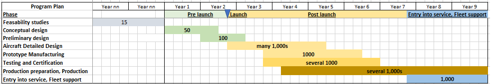
Figure 1. A generic new Part 25 airliner development plan. Source: Leeham Co. Click to see better.
IT Support for Development
We will discuss IT development support in a generic, vendor-agnostic manner. We cover a bit of IT support history, as IT application history is an important part of an existing OEM’s reality, and how this can restrict the free choice of an OEM upstart.
Development IT support history
Before computer-aided design support for development engineers became common, paper drawings with lines and instructions were the primary design documentation. Computers enabled the lines of electronic drawings to be drawn faster and more exactly, with 2D MCAD (Mechanical Computer Aided Design) support becoming common in the 1970s. It was still line drawings, but now on computer screens, which were later printed (or, actually, plotted, as the drawings were large pieces of paper).
In the 1990s, the change to working with 3D solid objects started. A bolt connecting two parts now had to be inserted as a 3D bolt object into generated holes in the equally 3D generated parts. Now, the designer had check of fit and tolerance matches. Adapted 3D models, called meshes, could be generated for strength, resonance, and thermal simulation.
The first airliner project that used 3D MCAD extensively was the Boeing 777. Output was still in the form of drawings, as factories and suppliers were unable to generate manufacturing data from 3D models; however, aircraft designers could see and check the design in 3D.
The drawing archives where replaced with database applications called PDM (Product Data Management) which had revision and check- in, check-out control with workflow support, configuration management (what data belongs to what aircraft version), search and presentation functions etc (“ find all the parts and show me the left wingbox structure with fuel system components of version 2C1 of the aircraft with all the design documentation”).
The birth of Product Lifecycle Management
The PDM served as a support system for the company’s R&D. There were PDMs for MCAD, Electrics (wiring, power electrics), Electronics called ECAD, and Software code management. Gradually, the PDM was expanded to support more parts of the company, now called a Product Lifecycle Management, PLM, system. It meant an expansion in scope, both upstream from design to requirements capture/management, specification generation and management, management of all project documents, including design simulation and test data, certification plan generation and substantiation, and data for manufacturing.
To support manufacturing, the PLM had to interface the OEM’s ERP (Enterprise Resource Planning, the company’s bread and butter system for sales/marketing/purchase/manufacturing/invoicing and economic control) system with data for Purchasing, Manufacturing planning and scheduling, and Quality control. The interaction of these systems is depicted in Figure 2.
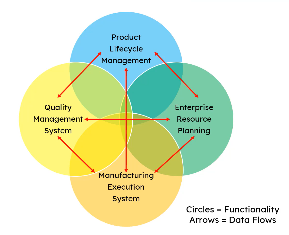
Figure2. The key IT systems supporting aircraft development and manufacture. Source: PTC video about PLM.
In Figure 2, Quality Management is shown as a system. The reality is that it’s more of a function that uses and stores information in PLM, ERP, and MES, depending on the context. It might have its own applications to generate statistics and reports, but the necessary data is accessed in the other systems, and the results are predominantly stored in these systems.
The PLM is the platform that enables company functions to access and control development data. A PLM typically has the following functions:
Cross-domain collaboration
- Manage MCAD, ECAD, Simulation, and Processes
- Manage relationships and dependencies
Change process management
- Manage the change process across the company
- Manage workflows that integrate your business logic, including design review and release
Product requirement management
- Capture, collaborate, and maintain requirements across organizations and suppliers
- Continually verify that product design meets the requirements
Configuration management
- Create and share a single, accurate product definition (a single truth)
- Empower stakeholders to control configuration and track changes as they make them
Visual product collaboration
- Enable the teams to use 3D models without needing a CAD license by offering viewer functionality with the appropriate rights for additions and changes.
Purchasing’s interaction with suppliers and the manufacturing BOM (Bill of Materials) is housed in the ERP. To complement the semi-real-time ERP, companies add a MES (Manufacturing Execution System), which issues and tracks shop floor work orders in real-time, feeding the ERP and Quality Management System with the work results and any problems that occur during manufacturing.
The Legacy versus New problem
Aircraft manufacturers produce products with up to a 50-year lifecycle. During the full 50 years, the Certificate Holder, the OEM, is 100% responsible for the product. It shall be able to develop, certify, and produce different updates demanded by the regulator, Figure 3. We described this in more detail here.
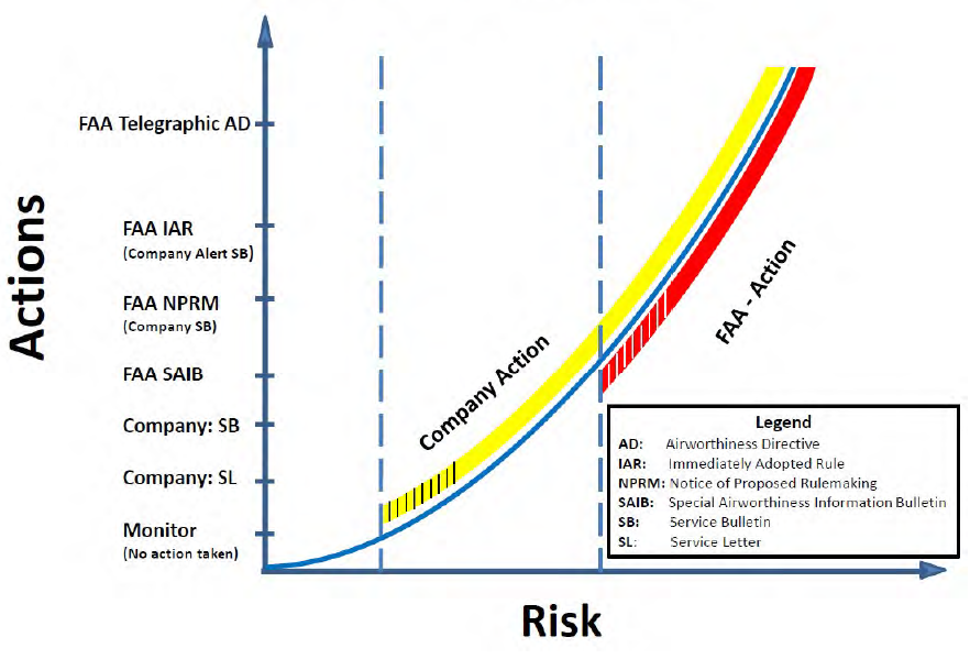
Figure 1. A graph showing how an OEM and FAA surveys the operation of an aircraft and takes action. Source: Boeing.
To manage all the activities we described above, every OEM has developed and integrated thousands of IT applications to support their operation (Major airframer IT managers have told us these have over 10,000 applications, due to the legacy support problem).
While the transition from 2D CAD to 3D CAD can be reasonably straightforward, as it primarily affects a smaller group of people, mostly in R&D, the larger applications, such as PDM and PLM, significantly impact various parts of the company with diverse needs.
In almost all cases, there is a history problem. Let’s construct an example:
Fifteen years ago, a decision was made regarding the integration of a supplier’s PDM system with the OEM’s own developed Manufacturing planning system. These two, which took some five years to run smoothly, will now be either interfaced with a new PLM system or replaced by it. It means a multiyear investigation of how you should interface to the new PLM or replace both PLM and your own manufacturing system. Once the decision is taken, it takes another five years to complete the change.
The ever-growing problem is that the IT Tools landscape changes major versions with five- to 10-year time horizons, and the aircraft that these tools must support has a 50-year life cycle. For some of the tools used in generating the aircraft, the vendor might have called end of life for this version of the application or the application altogether at half this time.
The fix for the time problem
The remedy for the above is to store as much of the generated data around the aircraft in as neutral and accessible a format as possible. There are neutral formats for documents (XML) and CAD (STEP), and work is underway on a neutral PLM format.
The problem is that the export of data from a vendor-specific application to a neutral format for storage or distribution almost always means a loss of fidelity of data. Any additional information has to be passed to, e.g., a supplier via data files, documents, or Excel files.
The dream of a totally integrated “digital connected enterprise” with only one large application world from a single vendor will remain a dream, according to those who work to get corporate heterogeneous environments to work.
An upstart OEM could theoretically have this luxury. Yet, it is unlikely that the upstart has the people, processes, and know-how in place to do all the design work in Figure 1 in the Detail design phase. It may need to rely on engineering consultants or suppliers to bridge the design knowledge and capacity gap. Suppliers will not change their IT landscape to that of an upstart. As a result, it creates an additional layer of interface between the OEM’s and the Consultant/Supplier’s IT systems, making the project more complicated.
Evaluating and choosing one’s own software tools is also complex. An inexperienced team could sign up for something without fully realizing the business implications. This is why tool selection deserves attention and requires stakeholder engagement at an early stage. A bad choice would be difficult to reverse once a large amount of data has been generated.
I am sorry for this interrupt post in this topic but this is too serious
“Spain and Switzerland canceled orders for Lockheed Martin’s F-35 fighter.” says Leeham.
It is false, Spain never ordered F-35.
“Trump tariffs beginning to hurt US aerospace companies; EU competitors to benefit” is the article.
Fixed.
We almost if not all realized that and it was pointed out if anyone had missed it.
I don’t think it was that big a deal.
The following link I think its worth an interruption. A horribly sad and fortunately not a tragic outcome. He was betrayed by his so called friends and its relevance was driven home once again on India 171.
https://archive.ph/BcaGB
Pilots do not belong on a pedestal, they are the same as the rest of us.
I remember Dassault Systemes Catia 3D was extensively used during A330/A340 project in the late eighties. It was also instrumental on the 777 design.
Yep, I remember that well.
Having been through operating systems from CPM to current Windows (11?) ungh.
Even at my low level, its caused major consternation. When the Sys Admin system will not accept a mirror image recovering from a crash for HVAC access, phew.
FedEx usually wound up with its own experts that could manage old operating systems. They were still running a DOS system when I left. The cost to transition was astonishing, just to have to transition again.
I can’t imagine the nightmare aircraft mfgs face when systems go unsupported.
Kind of makes you wonder if all the efficiency claims are totally bogus, what it helps in one hand is detracted in the other with expired systems and security insanity needs.
Our worst nightmares was realized when they put us on the FedEx businesses LAN. Our dept had no progression plan so we wound up running unsupported systems on a waiver. And yea, they loaded all their security stuff on an unsupported systems and crashes ensued. We no sooner got current and they were moving to obsolete our system because there was no succession plan.
That was just from a we want to see what our controllers for fans, boilers, pumps and Air Conditioning systems were doing (and fix them if needed). About as simple as it gets.
They took our stand alone network away from us even though it was not linked into anything else. Argh.
Complexity piled atop complexity.. not sure if the development
time can be speeded up any time soon, imo.
Thanks for this fine series.
Spot on.
We should remember that older programs in Catia V4 are far different than Catia V5. V5 appeared after Dassault jumped on the Solidworks bandwagon and migrated away from the old 2d extrude process. It is far more capable but is so complex that very rarely can 1 operator understand it all. What ends up happening is that areas of the design teams get really proficient in their small selection of tools where other design groups use a different set. In metallic structures we find the skin panels work well using sheets arcing around a radius while the the bulk of the stringers are 2d extruded shapes. The clips and brackets are done in fold up and there is t a lot of cross usage of the Catia tool sets making these parts in the same group. This creates silos of expertise that if not managed well, think 787, causes a lot of design inefficiency inside the group as well as promoting a non standardization of design methods. Think 787 41 section vs the 48 section where the basic design concepts are different because different companies did the work. Boeing never saw this coming because integrating V5 was a huge undertaking and this one wasn’t obvious. The end result was a body of the same work designed with different idiosyncrasies from nose to tail because nobody made all these design build teams talk to each other about optimizing the build process. Digital design is a great thing when you manage it properly. Managed incorrectly, you can build a lot of cost into the product and not see it coming
Very true. This is the value of systems engineering and integration, and its value shouldn’t be underestimated.
You sometimes see or hear systems engineering being questioned or disparaged (Elon Musk is particularly egregious in this respect), but it always makes me cringe. Those people are looking for trouble, and potentially a world of hurt.
Each Starship failure could be understood in terms of systems engineering. NASA puts a lot of emphasis on systems integration and engineering, for that express reason.
I don’t see NASA as anything other than a fossil.
Space X has done well with engineer it and then throw it up and see what happens.
Not that I have any like of Musk, but Space X sure has massively outdone NASA, Boeing and LM as well as Arianespace.
The evidence is overwhelmingly against this. NASA had a successful first flight of SLS and Orion, with Orion orbiting the moon.
That success was echoed by ULA with Vulcan, and Blue Origin with New Glenn. Like NASA, they have a systems approach that resolves most issues before they occur. And also ensures there is margin in the design, such that test flights only need to validate the margins. There is no question of successful operation.
This stands in contrast to the Starship program, which is not designed to systems engineering or margins, but rather is based on trial and error via rapid iteration, and the establishment of minimum performance.
Elon is quite open about this, he believes this is a faster method to an operational vehicle. Thus far, that has not proven to be true.
Just to clarify:
Originally planned for late 2016, the uncrewed first flight of SLS slipped more than twenty-six times and almost six years… the first launch was originally scheduled for 8:30 am EDT, 29 August 2022. It was postponed to 2:17 pm EDT (18:17 UTC), 3 September 2022, after the launch director called a scrub due to a temperature sensor falsely indicating that an RS-25 engine’s hydrogen bleed intake was too warm. The 3 September attempt was then scrubbed due to a hydrogen leak in the tail service mast quick disconnect arm…
OMG!
In late 2015, the SLS program was stated to have a 70% confidence level for the first Orion flight that carries crew, the second SLS flight overall, to happen by 2023… as of November 2021, NASA delayed Artemis II from 2023 to May 2024. In March 2023, NASA announced they had delayed Artemis II to November 2024, in January 2024 the mission was further delayed to September 2025, and in December 2024 it was announced that the launch was pushed back to April 2026.”
I’m a bit lost, is this what success looks like? The 737 MAX must be a success, too!
Lol, you really need to do better here. But as with the F-35, your purpose is not to inform, but to mislead.
The delays in the SLS program are what allowed it to be successful. If the design margins cannot be met, it doesn’t fly. That is the systems approach that succeeds.
That includes bad sensors, hurricanes, and unexpected damage to a heat shield. Issues are tracked down to root cause and addressed, as a matter of NASA safety culture.
Somehow your intrepid reporting has missed that NASA delayed Artemis 2 partly to even out launches, due to the delay in SpaceX HLS. For which we have nothing after 5 years and over $2B in payments.
And also missed the predictions that Starship with rapid iteration would beat every other super heavy launch vehicle to orbit. And yet the reverse is true, it’s dead last.
The reasons are as given above. Nor is that a new lesson, it’s been known since the Apollo era. But some people prefer to disregard facts and cling to beliefs, in opposition to the evidence.
@Rob:
Over budget, late, dinosaur not to mention the skinny stack abandoned.
Reusable Rockets and a Heavy Rocket . I go with what works
The art of marketing: turning a turd into the best you ever have! 😭
The 777X is definitely a “success”, so are the MAX 7 and 10, thought they face more delays with no end in sight.
That’s why the whole America is in this malaise: major infrastructure is either outdated or broken, investments in infrastructure are gobbled up with little progress to show, the astronauts were stranded in the Space Lab for nine months. But “it’s a success!” 😅 Boeing has negative equity and losing money and cash. But what a success! There’re too many who want to sell their narratives.
Take a good look around you, it’s hopeless because you refuse to admit the reality.
Have a nice day.
https://pbs.twimg.com/media/Gz2tW8fXYAAJ4uX?format=jpg&name=small
Pedro,
you are spreading a lot of invectives about you comment co-posters. Stop that as it’s again the rules of the comment section.
Sorry I meant the ISS
@TW: ironically all your criticisms are also true of the Starship program. The major difference is that SLS works, and it worked on the first try.
You may be conflating the Falcon and Dragon programs, for which NASA had considerable influence, with the Starship program, for which they only have a say in HLS.
These are very different programs and contracts. They are all public, so you are welcome to review them to verify this.
Starship is the first program Elon has conducted on his own, and the difference is quite apparent.
You mentioned reusability, but reuse depends on economics. There is a breakeven cadence required for return on investment. By definition, the Artemis program crew launches could never meet that cadence, as they are expected at 2 per year (as with ISS), surging to 3 if needed. Therefore SLS is not reusable, by design. To make it reusable would cost more, not less.
Just to clarify:
According to the CNN, “The moon rocket has been a major point of controversy in the space community for years, as detractors have called the launch system — which is *billions of dollars over budget — wasteful*. *Development of the rocket cost $23.8 billion between 2011 and its first flight two years ago, while initial projections expected that number to be more around $18 billion*. And one oversight official in 2022 estimated that the vehicle *would cost more than $4 billion per launch* for the first four Artemis missions. […]
On the heels of the revelation that Boeing is planning to lay off as many as 400 workers from its Space Launch System program, NASA has called the SLS megarocket “essential” to its Artemis moon landing program — sowing confusion about what, exactly, may change for both the launch vehicle and Artemis in the days and weeks ahead.
The statement from NASA comes amid widespread speculation that SLS — which made its debut flight test in 2022 — may be on the chopping block.
On the heels of the revelation that Boeing is planning to lay off as many as 400 workers from its Space Launch System program, NASA has called the SLS megarocket “essential” to its Artemis moon landing program — sowing confusion about what, exactly, may change for both the launch vehicle and Artemis in the days and weeks ahead.
The statement from NASA comes amid widespread speculation that SLS — which made its debut flight test in 2022 — may be on the chopping block.”
Why would a prime which enjoyed monopoly for decades think about how to be more efficient?
Not only that, BA has lost over $2 billion in the program:
“Years of technological and operational challenges have increased costs to develop Starliner, with Boeing reporting losses almost every year since it began developing the spacecraft in 2014.”
But what a success!
No doubt Ortberg is eager is cut losses, but where is the willing buyer?
Just to clarify (for real):
(noting that quoting from older articles is not the same as either clarification or comprehension)
OIG in their latest report estimated the SLS launch cost at about $2B. NASA had refuted the $4B cost and OIG agreed.
The $25B development cost for SLS includes the first 4 vehicles, as well as RS-25 engine acquisition for the first 6 flights (with spares), and SRB booster acquisition for the first 8 flights. As well as EUS development for the 4th and 5th flights, and advance construction on the 5th core stage. Which will carry the program through 2030, at the present rate.
That’s out of about $100B invested in the entire Artemis program through Artemis 5, which includes SLS and Orion, Gateway, a new mobile launcher, new moon suits, multiple crewed and cargo landers, lunar rovers, and various commercial robotic missions under CLPS.
It also includes upgrades to the NASA Deep Space Network, which services every mission outside LEO, and now incorporates laser communication.
This is a bargain by any standard. It’s a third of the cost of the Apollo program, and half of the cost of the Shuttle program, for significantly greater capability, and with 3 to 10 times better safety.
The HLS launch sequence will require HLS itself, an orbital depot, and between 14 and 16 tanker flights, all carried out in rapid succession. The cost of that is around $1.8B.
Upon reaching LEO, HLS will need to be refueled, to reach a higher orbit. Then be refueled again, before it can do a trans-lunar injection.
Once at the moon, it will have enough fuel to descend to the lunar surface. The first uncrewed HLS will not have enough fuel to ascend again, so it will remain there.
The second HLS will be crewed, and will need to have lowered mass and increased fuel to ascend again. Then it will be discarded because there is no way to refuel it in lunar orbit.
At a Senate NASA hearing last week, multiple witnesses testified that while the NASA SLS and Orion programs have successfully undergone demonstration and risk reduction, the SpaceX CONOPS is still immature and at a high risk level. There is no assurance it can be carried out as designed.
These are the facts, whether or not one chooses to accept them.
This is such a great series. Thanks again to Born, Henry, and Scott.
I experienced many of these technical changes during my career. As an undergrad in engineering, we were still drawing by hand. By grad school we were learning CAD systems and drawing electronically. By the end of my teaching career, the students were learning PLM.
I would add to the excellent information in this article, that the expense of transitioning these systems is very great. It was not unusual for the cost of the data conversion and port to a new system, along with the required verification and validation, to far exceed the cost of the software and the hardware.
This is true in the banking industry as well. The dominant cost is in moving the data between systems, because as noted, there is not really a neutral or universal standard.
Part of my job as a consultant was to identify, reconcile, and adapt to specific differences in data. Often that meant developing temporary bolt-on software that could merge historical data with the new system during the transition, until the older data could be phased out. I wrote many such systems over the years.
Another good point here is that aircraft products not only outlive their original design systems, but the staffing of those systems as well. There comes a point in your career when you realize there is a finite amount that you can do, and everything will have to survive you and be passed to the next generation. That becomes a major driver in decisions, it’s not so much about what’s best for you, but what will be best for those who follow you.
It’s awesome to see these aspects laid out in such detail, for anyone who wants to understand the process and how complex it is. Again, great job!!
Again good stuff.
Flip though is no one cared enough to follow what I did and when I left, there was no successor. Cost them tons of money. They did not care about me and I did not care about them (I did care about my work but spitting into a Hurricane was more effective than anything I said). My work was always done to the best possible standards.
Or as my brother says, will it bite me before I am gone? No, not a problem.
Slightly disappointed than the grand world of Finite Element Analysis and all that flows from it was reduced to “adapted meshes” – it is a great deal more than that, and arguably the FEM stress & fatigue, plus associated aero and CFD work, is more critical (and much more computing power) than the designers putting shapes into CAD. But somehow they always get the glory…
Anyway, just wanted to mention that the last thing we want is a single vendor, and in recent projects as well as open standards for files we’ve been using open source systems and programming languages to do some pretty advanced and complex development and analysis. There is more of a sense now that we need to avoid proprietary and closed-source things both for cost and to avoid lock-in or abandoned/dead standards rendering old data unusable.
Far beyond my scope but I agree on open standards.
I managed to skip some generations of Windows. Sadly, the tend was to drop the good stuff and put in bad stuff.
CPM was great as it was open source.
Someone sorted out the code area where you could toggle from single space to making it double space on Wordstar documents.
I then figured out the range (tiny increments) and inserted 1.5 spacing which was best of both (my opinion)
Try to do that with MS.
I am absolutely *NOT* a fan of MS at all(*)… but that’s actually pretty easy (you just have to know how to navigate their horrendous UI, although that’s got better with their focus on web-based UI): right click on text > paragraph > line spacing – you could also apply it to the default text style instead of per-paragraph.
(*) I learnt LaTeX furiously at uni after the third time Word ate a day’s worth of work on my dissertation. That’s also where I learnt discipline about using styles instead of ad-hoc formatting… it is so easy to apply or change a common, good-looking style for a whole document when you structure properly.
No-one want to pick up on the fact that the most heavy IT work is not in CAD but all the analysis? That was the topic of the article, after all… Put it this way, the supercomputer clusters and server farms are not wasting much time on CAD, which can be run locally on a laptop.
Good post, the lifespan of software is a major problem for everyone. For many aplicaciones new software doesn’t offer any improvement, companies try to avoid updating, but eventually you run into the “interface problem.” I know of some industries, who employ a lot of their own IT staff, who just use Linux
I have been surprised there has not been a mass movement to that.
As for the Boeing 737 single aisle replacement, with new wing riveters coming to Renton replacing the 1960s era Gemcor WRS (same track and lift panel systems) which is a major investment, its a safe bet the single aisle replacement aircraft will have metallic wings. So with no performance improvements from composite and/or thermoplastic wings along with no composite fuselage because single aisle fuselage are not scalable (thinner and lighter than metallic). Can they get lean mfg from part reduction from the 1960 era 737 aircraft?
You have put down a current and then extrapolated that into the future.
But no, The 777 had a riveted wing, the 777X does not. The 787 never did.
The A220 has a composite wing. Airbus work is all on composite wings and I bet Boeing as well. There is a big return doing a composite wing aerodynamically.
The Tube part, on the wide body probably yes (787 and A350) but not on the tube for a Single Aisle.
If Airbus had gone composite wing on the A320NEO, Boeing would have had to do the same. As it stands, both are at the same level and the economics are not better for one than the other in Single Aisle.
But because the MAX is riveted wing does not equate to the 797 having a riveted wing. Frankly its the opposite.
Trans
then why is Boeing spending over $100 million for new WRS at Renton if its short production run of less than 10 years for the 737? It would be less costly (like 20%) to just maintain the Gemcor WRS (1960 era) at Renton running for 10 more years?
Well the big boy finance guys at Boeing will have a better idea of payoff than we would!
Simply put its the cost of making the MAX until X date, and X date could well be 20 years.
I don’t have Boeing data at my finger tips (nor do you). They obviously looked at it and determined they needed to invest (not like they are rolling in dough is it?)
Obviously there is a balance of efficiency, production run and maintaining old st guff.
None of it means Boeing would not do a CRFP wing.
Wings are the one area there is a significant return as BBD showed on the C series.
Fuselages may well (at least that single aisle size) have updated materials that preclude composites that cost more. Wings are a shape and you can do efficient shapes with composites you can’t do with metal.
Nothing any different than when we redid the roof on the house. One and done and no patching along.
Trans
“None of it means Boeing would not do a CRFP wing.”
So why are the new Wing Riveting Systems coming to Renton going to have larger superstructure and deeper C Frame throat if its designed only for the current 737 wing? Original Gemcor WRS (1960’s) at Renton had a 60 inch C Frame throat…the new ones will be 120 inch. (it will be interesting to see how that 60 years old foundation at Renton with 140 ft wooden posts will hold up with the additional weight)
On another note, if composite (not thermoplastic wing) would require a massive investment in autoclaves unless they are going to use a process similar to MC21 black wing (“The production of these composite wings utilizes dry fiber vacuum infusion and automated lay-up robots, making it a unique technological achievement for Russian aerospace”)
a couple interesting videos
MC-21’s Composite Wings and PD-14 Engine – A Russian Technological Triumph
https://www.youtube.com/watch?v=dI5AA68lfOQ
The Science Behind the MC-21’s Revolutionary Composite Wing
https://www.youtube.com/watch?v=_LafrqcFmBY&t=1s
It may surprise you that yes I appreciate what Russian Aviation did on the wing.
Ok, quick disagress, I don’t differential between CRFP, Thermoplastic and Plywood. They are all composites. Gun world has the same issue, they think a Plastic stock is composite but disregard the Laminated stocks. One of the best aircraft of all time was made out of Plywood! (if they only had used Allisons with counter rotating props!)
That said, you are getting Abalone like in just repeating something. Put some logic into laying out a case if you can.
Boeing will use whatever build system it deems the lowest cost and meets the aerodynamics. Personally I doubt Auto Clave.
A220 has its issues as its wing build is so costly. Boeing and Airbus are both looking at that hard.
While I am not an engine expert, I have it on the best authority that Russian engines are way heavy for the thrust. So no, its not a technological marvel. Its what they got.
Clearly the Russians made a leap ahead in the wing build.
Just as clearly they have not put that effort into engines because they were relying on Western Aircraft and supplied engines for the MC-21.
Aircraft have flown with inferior engines. The chasm of flying and providing economical (full aircraft) in commercial service is vast.
Russia has always been able to focus on an area and succeed (Space, Tank Production in WWII). They could not build a reliable Washing machine.
In WWII they did not have an automotive industry. The backbone of their last 100 miles delivery was US Studebaker Trucks. The backbone of their air force was US supplied high grade gasoline and aircraft. None of which they could produce let alone quality and crank out Tanks and Artillery.
Russian fighter engines were as good as they come thrust wise. They never were longevity wise, but changing a jet engine is pretty easy and you just build lots of spare engines. They did not fail (yes a lot did) but mostly they wore out in a few hundred hours.
None of this in any way has any relevance on Boeing and future wing build. You assume they are stupid and they are not.
Trans
“None of this in any way has any relevance on Boeing and future wing build. You assume they are stupid and they are not”
You are right Boeing is not stupid, they made the decision to go with metallic wing for the next single aisle aircraft….you will have to wait and see in 10 or so years ps Boeing couldn’t fund the cost of building 70 plus a month single aisle with using autoclaves
Right Mel
Haha let me factcheck another questionable claim from TW, which looks more like myth floating around on the net (especially in America):
“The Studebaker US6 was not vital for the Soviet Red Army in WW2. In order to understand this, one must look at how many trucks were delivered, how many the Soviets already had, and when the lend-lease was delivered, and what they were used for. The graph (Which is from my own thesis regarding lend-lease in the USSR, based on US LL data, and H.G. Davie’s data about Soviet trucks) below answers three questions… ”
https://qph.cf2.quoracdn.net/main-qimg-9c238a3212d83a85d2ecbb8492773231-pjlq
“The backbone of their air force was US supplied… aircraft.”
Srsly??
TW’s motto: Boeing is always right… (except Dave after he’s done)
Pedro:
You really do not have a clue do you?
Shades of Deborah Harry
That Reply Guy!
Oh BTW everyone knows, (well, except a few here) how well the finance bro of Boeing ended up costing it tens of billions.
Airbus is serious about replacement of the A320 and manufacturing is a concern, but they are meticulously building their case. OTOH what has BA done in last two years?
What case do you need to build?
As long as Boeing does not move Airbus does not have to either.
And why would Boeing move? It not like you get a big LEAP out of it.
The days of 20% gains are gone. Airlines are still staggering under the engine debacles.
As long as Airbus maintains its dominance, why would they move?
Boeing has no money for adventures. Happy with the current standoff.
Last time, Leahy made a bet and cornered Boeing. Will history repeat itself?
From a *true* genius:
“The difference between genius and stupidity is that genius has its limits.” 😉😲
I need that button!
I think in ranking short term profitability, pushing out investment, securing executive bonusses, creating share holder value, protecting local jobs, the public pressure & urgency to reduce environmental polution by aviation is higher on the list in Europe than in the US. Airbus is pushed.
Sitting waiting cashing wouldn’t be acceptable.
Not sure I get that but if I do, we can only see what they do in the future.
Airlines are tired of new engines, they want mature and therefore you are not going to get a new launch for at least 10 years.
No matter what Boeing does, it’s always right!
From LNA:
“… the clock is ticking toward program launches anywhere between 2027 and 2030”
Who forgets to read LNA? Hmmmm…
👇👇 😅 Bookmark this! Remind me in 4 and 5 years.
“… you are not going to get a new launch for at least 10 years.”
David.
Getting a part reduction thru the use of lean on the 737 is doable. If you consider that the 737 fuselage is basically a buttload of shims flying in close formation, yes, lean can reduce part count. Boeing did it on the 767 by changing from the finger splices at all the stringer splices at the barrel joins. There are 72 stringer splices at the join of each fuselage section. The 41/43 join, 43/45, 45/46 and 46/48. On the 767 They replaced them all with machined terminal fittings in the Paddle Fitting Program and went to sheet metal internal skin splices between the terminal fittings. We were the initial adopters of a process to drill thru wet sealant without disassembly for deburring. we proved chips didnt exist. The implementation of Seti Tech pressure foot drills allowed the team to do this. we added 90 pounds of fittings to the airplane in the tradeoff and it came close to a net zero weight change after all the SM details were subtracted along with tens of thousands of rivets. This eliminated freeze plugs, skin changes and a pile of MRB action on top of pulling 4 MDAYs out of the factory flow along with 3400-man hours of labor per plane and well as over 4000 sheet metal detail parts. This project was instrumental in creating the slots that FEDEX used to buy their last large Freighter purchase. The reduction in total cost sealed the sale. I lead the Planning portion of the effort.
I’m still wondering why Boeing didn’t do a 767 NG.
The 767 is significant (25%) lighter and smaller than 787 and A330. The 400ER and freighter/ tanker variants took care of cockpit, system and wing upgrades, new interiors were available and PW/GE offered new engines.
Boeing itself identified the emerging NMA market segment. The US big three asked for it.
Looking back I conclude Boeing made a bad decision, blinded by Dreamliner.
And not only looking back. I promoted the idea already 19 yrs ago and many others, including Boeing internally.
https://www.flightglobal.com/programmes/boeing-examines-genx-powered-767-x-for-cargo-and-passenger-roles/134757.article
Probably Boeing would be in better shape if they had the stable cashflow from this existing production line.
Boeing isn’t going to introduce an intermediate aircraft that would compete with two of it’s three products. Unless those products were being phased out for another reason.
The 767 couldn’t fully address the markets of the other two, it could only subtract share from both, in the middle. With the added expense of another product line, since it couldn’t share those either.
In order for that to be profitable, the 767 would have to take greater share from Airbus in that same market space. It’s not clear at all that would happen.
I’m sure that Boeing has greater knowledge of this than we do, both in terms of market and cost. They decided to focus on their existing lines.
It’s one thing to recognize that an aircraft could fill a space in the market. It’s another for that aircraft to be profitable.
If the profitability was there, we’d see airlines still wanting to order the 767. We don’t really see that.
Lets be honest, if Boeing had greater knowledge of the products and markets, they wouldn’t be where they are today, #2.
-$50B in the bank, scruntinized by global authorities, 4 types delayed >6 years and leaning heavily on Mr. Trump as #1 salesman, financer, customer and tarrifs bully.
In my opinion groupthink was strong in Boeing 2003-2018.
That take is now dated.
The big question has been if airlines would buy a 767NEO in numbers and as Rob said, not hit the 787-8. I do think the -9 is a different category.
You still have to do new engines and those are heavier.
Do that and you need to make it more efficient which is a lot of wing work and maybe fuselage clean up.
You also see airlines flying -8 and -9 on short routes. So Rob may well have it right you hit the -9 as well.
Delta was the only one you could gain, they both wanted a product in that segment and had no Boeing aircraft in it. But Delta does not make production.
A better case could be made to have done a 767NEO and not the 787 and gone with a seriously tested GTF engine. You would have gained a new aircraft efficiency wise at hugely lower cost.
I think Boeing has 30(?) 787-8s in the backlog and the 788 & A338 are 35t heavier then the 767-300 (84t).. 35t ! Put that in a simulation model, stating it’s a 787 competitor is factfree.
A 767 NG would have been a low risk affordable efficient gate cat D aircraft with no direct competition and strong leisure (8 abreast), cargo, tanker and medium range markets.
EIS in 2015 would probably have had 600+ flying today.
The Airbus 3A30 neo owes much, if not all, of its success to Boeing’s delays with the 787. The A330 was at the right place at the right time. The 3+ year delay of initial service left an enormous gap of demand that the A330 filled. Later 787 delays, which Boeing is still working through, sold even more A330s along with a whole pile of A350s.
How Boeing, by ending 767 production, dodged a costly modification:
> Following the 1996 in-flight explosion of TWA Flight 800, the FAA introduced new rules about flammability reduction in 2008. In 2012, Boeing requested an exemption for the 767 from new wiring separation rules that would prevent ignition sources, because design improvements it introduced fell short of meeting such rules. One of the justification by Boeing: changes to the fuel quantity indication system would require a halt of delivery by three years as production of the 767 model was expected to end shortly. FAA gave the manufacturer three years to have a compliant system while deliveries continued. In 2014, Boeing, without a new design available, asked for and received another time-limited exemption for just the 767-300 and 767-300ER until 2019 when commercial production was expected to cease. But in 2017, with continual demand for the 767-300F, Boeing asked for another exemption up to the end of 2027, well past the revised production end date.
Pedro said……
Boeing, without a new design available, asked for and received another time-limited exemption for just the 767-300 and 767-300ER until 2019 when commercial production was expected to cease
In case you missed it. Commercial production of the 767 is not scheduled to end in 2027. The 767-2c, Continues in production beyond that point. The C in the model designator stands for Commercial, and it is the Commercial Off The Shelf 767 model forming the basis for the KC46 feedstock supply…… Check the TCDS, and keep your word salad half truths to a minimum please…..
Haha the word salad came straight from the Wikipedia. Talk with them.
Have to remind you that my quote continued with the following:
“But in 2017, with continual demand for the 767-300F, Boeing asked for another exemption up to the end of 2027, well past the revised production end date.”
Comprehension FAILURE! 🙈
Also read this and tell me which part Sean wrote is “word salad”!
https://aviationweek.com/air-transport/safety-ops-regulation/faa-faces-tough-choice-latest-737-7-exemption-request
🤣
Pedro.
It doesn’t matter if you regurgitate Wikipedia or not YOU are responsible for your posts accuracy. Telling me to go fix Wikipedia isnt my job, I am not responsible for policing your dubious sources. It’s funny that you give Trans craap about the pedigree of his sources but you seem to hide under the Teflon blanket of Wikipedia when you dont get it right…. Lastly, you posted a link to a 737 news report that had absolutely nothing to do with the 767 issue being discussed. You shure put a lot of effort into avoiding the facts and data that’s easily available to all, so please spare me the word salad quotes in your word salad responses, I laughed so hard root beer flew out my nose…..
No. The report from AW contains everything you have to know about the 767. Sean wrote the story, editors put the title. It’s not my fault you failed to access the article, and there’s nothing I can do. All you haveto do is go ahead and read it yourself *before your reply*. Your inability has nothing to do with me or the correctness of my post. Don’t make such a fuss talking about word salad when you didn’t read the article from AW and see where your word salad come from. That’s the basic requirement to have a fair discussion. There’s nothing that shown you intend to have a fair discussion.
PEDRO.
I read the article you posted before I replied. I EVEN read it a second time…… Here’s what thw article says
Boeing’s marathon-like push to earn approval for its 737-7 likely no longer hinges on demonstrating that the model meets all required regulatory standards but instead on convincing the agency that a known noncompliance should be permitted for a few years while the OEM develops a permanent fix…………..
There is nothing in here about the 767 zero zip nada.
Enjoy the evening and try harder because you are becoming less. Believable each time you add another layer of fog…..
Your insistence that Boeing isnt loading 38 fuselages a month into the GAL shows your lack of understanding of the entire assembly process. Not looking at the first 199 days of a 210 day process is the seat of your problem. But forgive me for failing you, Ive never been able to make a horse drink no matter how hard Ive tried…..Now if you excuse me I’ll spend my time replying to serious writers.
Lol. You consider that the snippet you accessed as “reading the whole article”. Give me freaking break!
I’ve told you repeatedly it’s not my problem if you didn’t read the article.
What I can tell you is 767 is mentioned eleven times in the article. Start from the second mention. And the Wikipedia page is a nice summary of what’s in the article. Don’t waste my time anymore, unless you finish reading the whole article.
Agree- there should have been / should be a reengined 767.
Great plane.
We agree on that, I disagree on the 767NEO post the 787.
People keep bringing up the 757 and Boeing made a decision based on economic reality there as well.
Running in parallel with all this at the time was the slow liquidation of the company. Hopefully that is gone. One thing about not having any money, you can’t piss it away again.
Vincent,
This is invisible to you, but it would be exceedingly difficult to re-engine the 767 today. There are 2 reasons. First, all the fuselages built today lack windows and are assembled with terminal fittings in place of the sheet metal stringer splices. Second, around the time we decided Ethiopean would get the last passenger airplane and the passenger 767 was no longer offered, the engineering changes that would have been driven for Rejection tag corrective actions were deferred indefinately and the rejection tag C/A extended as required to get to the end of passenger airplanes effectivity. The result of this means that the engineering effort to re engine the airplane would include the recreation of all the fuselage panel assemblies to be compatible with all the new terminal fittings in use today. that’s a 100% new engineering package for all the fuselage skins, new stringers, all the electrical systems need to route and clip, systems, IFE controls, vac waste and anything hanging on or connecting to the skin panel assemblies will have new installation drawings needed. its huge and gets bigger when all the unincorporated MRB initiated engineering needs to be reviewed and worked for change incorporation moving forward from the PRRB freeze date long ago. Its not so simple going back in time. If the call were made at the time that the passesnger plane offering stopped, it would have been a slam dunk and the a330 neo may have been stillborn.
Keesge.
There were a number of us screaming for a re-engine of the 767 for a long time. Finance killed it because their vision of the skyline chart and perception of future market size wouldn’t make it pay…… I’m afraid that this is the same analysis that prevented the MOM from launching.
Eight-abreast in a 767 would be a real squeeze. Loved the 2-3-2 in its economy section; one of the many things that
made it such an attractive choice.
Vincent
Great recollection of the old gal. The designers either lucked out or actually designed a fabuluous transatlantic bird that cubed out when it grossed out going Paris to NYC
Thanks. I used to fly on the 767 Chicago – Stockholm, sometimes getting deiced more than once, hence long delays on the ground; no problem! What a capable and confidence-inspiring plane.
Vincent.
I really think the 767 is a masterpiece of metallic structures. Its simple, light, doesnt have many maintenance campaign issues and is just a robust truck of an airplane. In my career, I think I enjoyed it the most.
Thanks for that 767 info, PNW.
I’ve seen a number of photos of ‘wrinkled’ fuselages in 767 which suffered hard landings. Evidently some models are prone to this. I guess it’s repairable.
Thomas Benedict wrote
I’ve seen a number of photos of ‘wrinkled’ fuselages in 767 which suffered hard landings. Evidently some models are prone to this. I guess it’s repairable.
Thomas.
You have to hammer the 767 to get the classic splice wrinkles. The circumferential stiffness of the airplane peaks on the fuselages where the old style stringer splices join the barrel sections. Its a big repair requiring the fuselage to go into large 4 inch wide cradles to support the fuse while you undo the stinger splices, remove the damaged skins and put all the splices and skins back together. this glosses over the work to gain access to the damaged area. Until I left Everett, a 767 joined with the paddle fittings hadn’t been bent enough to require a splice repair. The paddle fittings are not as stiff circumferentially as the sheet metal stringer splices and buys more damage tolerance by not focusing the loads in 1 place.
Yeah, United Airlines agrees with you on that. They’ve been quite successful with their subfleet of premium seat heavy 767s flying across the pond. I think they have 167 seats in them. That’s a great way to make money with older aircraft. Lufthansa does the same thing with 747 and A340.
+1. Delta, too.
I had a holiday trip with A330 to destination and back on an eight abreast 767 (TUI). Plane horrible.
The 767 was beaten by the A330.
+1.
767 is too narrow for 8-abreast. Sardine can in that format.
Boeing made 37 new x 737 in August. 42 delivered with the 5 out of the storage pool.
I would say that Boeing is at Rate 38!
I see, 37 is the new 38! Who the hell preached not that long ago when the numbers were bad, not to focus on the output of a single month?
+1
Wasn’t that one telling us over and over that it’s the long-term average that counts, rather than a snapshot impression?
HEY PEDRO.
When I showed you how the acceleration of the 737 line rate was working, I specifically said they weren’t at 38 a month yet, but the indicators looked like they very well could be loading at 38 on the front end where it is roughly 200 MDAYs from rollout. The delivery of 37 this month reinforces my observations. Go back and reread it. Your response was a string of gibberish attempting to bend facts. Let’s press on with that conversation, it was looking like a great discussion until you printed the word salad
IIRC Boeing said they achieved 38 per month in May. Check that out. History is inviolable. Do you have a time machine to turn back the clock?
“Boeing said it rolled out 38 new 737 MAX aircraft in May, hitting a production target it has been working on for more than a year.”
https://ca.finance.yahoo.com/news/boeing-books-303-orders-hits-150604308.html
With 20/20 hindsight, i see that as well coordinated Just in time for the Paris Air Show. If not for an unforeseen event, Ortberg and Pope would have basked in the limelight.
I wonder how often poster believes they know everything? 🙄
PEDRO.
Your continued use of a seriously trailing indicator IE deliveries per month is the root of your erroneous assumption that Boeings lying about reaching a line rate of 38. The wing spar chords and the wing skin blanks are made by the mills for Boeing, there are no other users of this stuff, so the supply chain length matters. The supply chain for all the bones making an aircraft last time I looked is around 200 MDAYS. An MDAY on the callendar is a monday thru friday non holiday. Weekends are non counters. This means 200 mdays can approach 10 1/2 months. You are focused on the Fuselages in the FAL. Cool, thats the last 11 MDAYs of the 200 MDAY product flow/build process. Its also a seriously lagging indicator to describe system performance. If you wish to keep score that way, its your right to do so. If you want to say Boeings not on its way to stabilizing at 38 a month, feel fine to say that. The facts are that delivery’s are slowly accelerating as measured by your lagging indicator while those of us looking at the system as a whole see a different story. The truth after you look at all the available data as well as recent performance is that it is far more likely that the line is actually performing beyond what the current deliveries indicate, is it 38 today, it entirely depends on where you look and what metric is used. I can guarantee you that my perception of line performance is closer to reality than your focus on only the last 11 MDAYs which would be the last place where a stable 38 a month line would show it. As far as Boeing saying what they do about a stable 38 being achieved, or soon to be there, They can be absolutely correct while you dont see it using the lagging indicator you point to. Your use of the delivery count doesn’t make Boeing wrong. It also doesnt make you wrpng as you are relying on what you can see to make a deision. Do I have a fix to get you to better understand an exceptionally complex process, Im not sure because it would require a reframe of how you are looking at things and Im not sure you want to make the jump even if the storys there for ya. Changing hats here for a second. I also will give you this point without contest. BOEING ALWAYS PARSES SHIT TO THEIR ADVANTAGE, I hate this because there are times it pushes them into nonsensical positions. IN THIS CASE, I know that Boeing would use the chance to say that initial loading of the front end of the line at the first WIP bump of a schedule to get to 38 a month would be announced as achieving that. I said the truth is somewhere in between. The funny thing is that Delivery rate would be also be a lagging indicator on a rate cut as the entire system would slow before you saw an output change….. Your inability to face the truths of the facts presented is puzzling. But then again you use Wikipedia as the gospel and when called out all you have is telling me to go fix Wikipedia. Tedlon works well for you
It’s pretty clear for everyone what “roll out” means in English. BCA can’t loading 38 fuselage onto the FAL while the output continues to lag. The line is fixed and each fuselage in the line occupies a position.
Your post is contradictory.
“BOEING ALWAYS PARSES SHIT TO THEIR ADVANTAGE, I hate this because there are times it pushes them into nonsensical positions. *IN THIS CASE, I know that Boeing would use the chance to say that initial loading of the front end of the line at the first WIP bump of a schedule to get to 38 a month would be announced as achieving that*.”
Either Boeing is misleading outsiders or not, it *can’t be both*.
It’s also pretty clear editors of Wikipedia know better. I read the AW article, you haven’t. Period.
Boeing has said theres a a range of production processes to cover the 38 pm rate. Media often dont report accurately the specifics
AirCurrent says it most clearly, they are only at 2)
1) pace at which it begins wing production
2) pace when it rolls out the planes from FAL
3) when it delivers at the 38pm rate
https://theaircurrent.com/aircraft-production/boeing-rolls-out-737-max-38-per-month-rate/
Ortberg said in May (quote) We are close, very close to getting the monthly rate (unquote)
Please correct your news feed false claims Pedro
Duke
“Boeing said it rolled out 38 new 737 MAX aircraft in May, hitting a production target it has been working on for more than a year.”
Wonder why BA didn’t correct media reports if it thinks they are wrong! Because it’s intentional?
Apparently BA’s press release mentioned “roll out” without further explanation what exactly they meant. 🙄
Smoke and mirrors?
https://boeing.mediaroom.com/2014-01-24-Boeing-Rolls-Out-First-787-Dreamliner-at-Increased-Production-Rate
Duke
What BA and media said about “roll out” definitely is not the same as what that poster talked about: input. It’s the opposite.
And BA held a “celebration” for the occasion! 😁
Media hardly ever correct their stories , especially when its much the same. The stock response is ‘stand by their reporting’
Anyway its YOU thats being corrected now. Take your own advice a fix your mistakes.
Even if it reduces your UFWD kpi rewards
Reuters: Boeing Defense plans to replace striking workers with new hires
Oh, that should work just fine. /s
Mind you, the wing sections of 777x is made at St. Louis, affected by the strike. So I guess the 777-8 is not happening any time soon.
Does it look attractive enough? Not sure why the top mgmt think that’s good enough.
> The offer rejected by St. Louis-area workers included a 20% general wage increase, faster wage progression, a $5,000 ratification bonus and more vacation time and sick leave.
are made*
Pedro wrote Mind you, the wing sections of 777x is made at St. Louis, affected by the strike. So I guess the 777-8 is not happening any time soon.
NOT QUITE TRUE… The production rate of the 777X is currently hovering around 1 a month. The movable surfaces of the 777x wing that are built in St Louis are secondary structure easily added to the airplane out of position if necessary. But that would only be necessary if the elasticity in the line was unable to make up the lost MDAYS involved with the strike. So far they are out around 15 MDAYS out of the 210 ish flow days from long lead close to rollout. There’s a huge amount of time work this issue, so while it is a minor concern today, your pronouncement that the 777-8 not happening soon is quite childish. Those of us whose career was mitigating assembly issues on the actual live line building real aircraft know better than to worry at the level you try to whip up……
As i mentioned previously, BA & its CEO had been talking up fancy production rate for like three years, 31/mth, 38/mth, 42/mth etc. My understanding is either BA’s supply chain had heard too many boys crying wolf and stop listening to BA or its supply chain is in a worse shape than most expected, that BA still falls back to its old habit of more hype (“rolls out” 38 aircraft a month) than substance when it’s real rate is quite a bit lower. Tell me how many outsider care about AB’s delivery numbers, how many outsiders care/know about AB’s rate of production. The same applies to BA especially you are unable to shed any light of the real production rate of BA. Empty talk means little.
It’s unlikely this will actually happen at scale, if it happens at all, but it has a good chance at getting negotiations going again. They may be hoping to get current strikers to cross picket lines, although IAM has pretty good solidarity.
But there’s no way they can replace all those workers without months/years of delay on affected programs.
Thanks to @PNWgeek for the informative posts, I’m learning a lot about production metrics. I don’t recognize all of them so am looking them up as they appear. They really help to add clarity to what’s going on with Boeing.
Rob…..
Your welcome.
I also find your posts quite useful. This is a complex business and there are many here that contribute to the body of knowledge.
Speaking of the 737-7 (and -10): any recent updates on their estimated certification date, and EIS? I’m now figuring late 2027 EIS for the -7, and a couple of years later for the -10; call it 2030 for the latter.
These are guesses, and we will see.
We don’t have any estimates, we only know what major tasks are remaining.
For the 737-7, there is the de-ice solution, which Boeing is fine tuning in the wind tunnel. It’s hard to see that taking multiple years.
And the SMYD waiver which is either going to be approved by the FAA, or not. No insight into that, but if it’s approved, that doesn’t add any time. If it’s not approved, then it depends on how quickly Boeing can get the changes separately certified, but it could be a year or more.
For the 737-10, the SMYD waiver is not required because the 10 has fully integrated the EASA improvements, but the de-ice issue is still applicable. Plus whatever else remains in certification, which again we don’t know what that might be.
So I’d be watching for the FAA waiver decision, as well as progress on the Boeing airflow testing for de-ice.
A few years ago, Mister Calhoun from Boeing said the “deice solution” for the 737MAX would take “six to nine months” to implement. Yet here we are..
I heard they got the solution wrong. To you, does it inspire confidence?
And we know the reason, they discovered inlet flow variations for the redesigned cowl, in certain regimes of flight.
As I noted, that happened also for the B-52 re-engine project. It’s why you test. So you go back into the tunnel and tweak the design. Most engineers understand this.
Flow interactions are not always obvious. If you are heating the cowl surface, that creates additional boundary layer effects. It’s possible to trip the layer into turbulence with heating.
In addition you can get pressure deformations of the inlet geometry, which was the B-52 case.
I don’t know what this problem was, but I know it’s not that unusual to find variations in testing. My guess is they have to demonstrate margins across all regimes of flight. So it could just be insufficient margin.
In the first SLS launch, Boeing found a resonance in a strut for the transonic range, that lasted under 10 seconds. The solution is simple, a fence to prevent a vortice from forming. But many hours of testing to know where to put the fence, and then establish that the fence won’t introduce a new issue.
It’s easy for non-engineering folk to find fault with delays and costs. It’s a different matter as a professional engineer, to demonstrate that the work is fully vetted.
This was the point I made earlier about the importance of systems engineering. You might design a cowl and not recognize the impact of the boundary layer on the engine, unless you have a systems approach.
That being the case, why would the senior person from Boeing make a claim that they had no way of knowing they could meet, timeframe-wise?
As I said: here we are, several years later, with no solution at the ready- despite Boeing’s unrealistic previous claims.
“We’re workin’ on it..” 😉
Rob.
Who was it that said “Space is hard”?
Vincent, you’ve provided a good example of why conflicts constantly erupt here.
Boeing is criticized for not doing the needed work to ensure quality, and also Boeing is criticized for doing the needed work to ensure quality.
As I pointed out to both Scott and Pedro, when a person stands on both sides of an issue and criticizes, it’s pretty obvious that the true objective is the criticism itself.
And consequently, that criticism won’t be considered as reasonable or accurate by others who are criticizing with the objective of improvement.
Another aspect is the absence of factuality or understanding in the criticism, which also seems to be immune to the facts and understanding provided by those same others.
I just explained that the issues arose in testing, and your counter is that the issues should have been foreseen. But if they were foreseen, they wouldn’t have arisen in testing.
I also explained that issues commonly arise in testing, otherwise there would be no reason to test. No one designs something with a flaw, so that it may be discovered in testing in order to triumphantly prove the boss is wrong.
A thorough thought process should identify this contradiction before it becomes a statement. Which is why only a select few here make statements like this.
@PNWgeek
What’s interesting about the SLS resonance issue, is that NASA won’t tolerate an undocumented resonance, because of the risk of overlap with a documented SLS excitation frequency. That’s the purpose of modal analysis and testing, which intertwines with many disciplines.
With Starship, two test flights failed consecutively due to resonance issues in the propellant piping to the ship engines. In the internal engine bay video, they were called “the organ pipes” because they were visibly vibrating.
The SpaceX approach was to strengthen attachment points and welds to the point where the piping would survive the maximum engine burn time. But that didn’t work, and the ship exploded again. After a second round of strengthening they did survive the flight. But with what margin? No one knows.
This shows the difference between mitigating root cause and mitigating symptoms. After the shuttle accidents, NASA is required to do root cause analysis.
That’s why it’s hard to accept criticism of NASA doing things properly, when the alternative is so clearly on display.
Rob.
Another interesting subject right there with resonance is sonic fatigue. As I understand it, the acoustic energy from shock waves impacting the surfaces of structures can rapidly cause ageing of them very similar to fatigue caused by repetitive cycling of loads. Go figure.
@PNWgeek:
Yes, that’s why Starship is abandoning the flat cooling plate on the launch mount, and is now building true flame trenches. The acoustic shocks coming off that plate were enormous and quite obvious.
The thing is, NASA published a study in 1962 that evaluated various geometries for flame deflectors, including the flat plate, at different rocket diameters and thrust levels. That study showed for Starship levels of thrust, the only solution was a trench to dissipate the acoustic energy. There’s significant risk of payload damage without one.
I would add as well, that on Friday the interim NASA Administrator said that “sometimes we can let safety be the enemy of making progress .”
That has a lot of people cringing, because it reverses 20 years of safety culture at NASA, after 14 astronauts were lost.
Even worse, he is also over the FAA, which like NASA is heavily invested in safety culture. One only needs to look to Boeing to see what happens when safety culture is lost.
Boeing is now rebuilding that culture, which is a great thing, and the FAA has mandated it. So difficult to understand how the reverse view can be taken at NASA. We have to hope that saner heads will prevail.
What happened to other cowl designs by BA? They got “lucky”? I hope that’s not the right attitude for BA/BCA.
Rob
How come you failed to see a critic like me is focusing on BA’s habits of overpromises and under-achievements? Who tell BA to say the MAX 7 will be certified in a year? Who the hell told WN repeatedly the MAX 7 would be delivered soon in 2021?
In 2025, why would anyone take BA’s words at face value?
Pedro, the answers to your questions are in the documented factual record, and have been discussed here ad infinitum.
You don’t accept those answers, so you just keep asking the same questions, over and over again, hoping the answers will change. But they never do. The truth is funny that way, it’s not altered by repetition.
This behavior is pretty much exclusive to a small select group here. But the rest of us are not accountable or responsible for it.
I outlined for Vincent what the purpose of that behavior is, and the contradiction inherent in it. That’s all we can really do. The rest is up to you.
Rob.
I brought up sonic fatigue because sections of the 767 fuselage skins are flag noted as sonic fatigue warning areas. This is primarily the zones around NACA inlets where the local boundary layer can detach and reattach at very high rates depending on Alpha and Yaw displacement. IIRC the impulse frequency was close to 400 hz and the DB could be over 100 when you aggravate things by changing fasteners heads on MRB repairs in the flow zones. Adding trip sources was no bueno…. Flush Head Hilocs were actually not flush enough and shaved rivets which more readily followed the skin radius were the first line of defense to aero tripping the boundary layer accidentally
Rob
Just to clarify:
You avoided my point: BA’s (bad) habit of overpromises and undedeliver.
Over the years, BA had successfully designed cowls. But they faced unforeseen issues only for the MAX, why?? Engineers know about the up and down side of each proposed solutions, shouldn’t BA have plan B and plan C, etc under evaluation? Why not?
You posted non-replies dressing up with word salad as replies. Yeah, we all know what’s your position and stop wasting time by posting non-replies. Who is this small group who repeat with non-replies. Readers here can determine themselves.
@PNWgeek
Thanks for the information about the 767 cowlings. I never considered the effect of inlet turbulence and vortices on the fuselage, but it makes sense that if they disturb the inlet, there could be external effects as well.
That’s a good example of what Ortberg said, that there are complex flow dynamics around the inlet and the cowling, and it’s not a trivial issue.
I really appreciate your factual contributions here, we all learn something from them.
Rob
I remember helping out with the aft fuselage guys when they had a hell of a time back in the 48 section. They were bringing air into the fuse with a tiny 3/4 inch composite duct replacing a welded up aluminum one and they created a sonic issue. The composite duct lacked the necessary stiffness and the duct would occasionally get an adverse flow trip event in the rain. It would vibrate and fail causing a decomp event. So they changed back to metal immediately. The only saving grace was that the failed duct leak size was masked by the outflow valve that had enough range to keep things in the green. Flow issues are never straight forward. A lot of it is just plain voodoo, everything needs testing and clearing the dark corners of the envelope isnt a slam dunk
Thanks, that’s wild, but I can well believe it.
It sounds similar to issues Boeing has had with drain masts on the KC-46 (which is based on the 767).
Seems like it would be a simple issue, but I’ve seen images of a KC-46 with a purplish-white coating sprayed on the underbelly. When I asked a boomer about it, he said it was a test of the fuselage fuel tank drain mast, to see how the fuel is dispersed in the air stream, and where it ends up on the fuselage, under different conditions of flight.
So they have a dyed substance which mimics the properties of jet fuel, and they pump it out the drain mast in various flight modes, then land and image it, then wipe it off and try again.
They also try breaking the mast off at different lengths to see what happens in a failure mode.
That’s pretty low tech but there is no question about the results being representative of reality. And it’s pretty important to know where drained fuel actually goes.
I believe they’ve also had freezing & cracking issues with plastic masts.
About the 767 NG development, as a fast/ low cost alternative, that never took off:
** An 8-abreast layout was widely used on 767s in European leisure operations, typically on flights of up to 4 hours. These aircraft were flown intensively, often pushed to their life time limits, without true 1:1 replacements.
** Re-engining studies for the 767 were explored more than 25 years ago, including concepts using the GE/PW GP7000. For the past two decades, GE has also promoted the GEnx as an option, similar to the bleed air, smaller version used on the 747-8.
** The rise of the A330 in the late 1990s drove Boeing to launch the 767-400ERX and, shortly after, to develop the same-size 7E7 (which became the 787).
** Key 767 modifications have gradually been integrated through the 767-400ER, as well as the tanker and freighter programs.
Ultimately, Boeing chose to wind down passenger variants of the 767. That decision was IMO shaped by:
** the $ecure 25-plus-year congress backed USAF 767 tanker contract
** optimistic expectations for 787 production ramp-up, dominance
** the anticipated launch of a Middle-of-the-Market (MoM/NMA) aircraft
** the assumption that Boeing’s long-standing customer base would remain loyal anyway
keesje
** An 8-abreast layout was widely used on 767s in European leisure operations
As I remember only TUI squeezed their sardines in that can. Condor had 7-abreast.
767MAX would have had the same problem as 767 vs. A330. With or without new engines A330 is the more efficient aircraft on most routes.
787 production was supposed to be far cheaper than 767 production therefore no 767MAX.
Off topic
One day, can LNA shed more light about Mitsubishi’s MRJ/SpaceJet, why they took so long… and is this report of JCAB/MLITT lacking experience of certification about right? Wink, wink.
I was lookin up on the net, and found this piece:
“Boeing is starting to see significant flow improvements in 737 MAX production, Boeing Commercial Airplanes CEO Stephanie Pope said July 21. “Production rates are increasing meaningfully month by month,” Pope said…
“The company is also making progress on modification of the engine anti-ice system on the 737 by now having chosen a design, Pope confirmed. [Everything looks good until I screeched to halt upon reading this 👇] The new design could be certified in early 2025, Pope indicated.”
Word for word no one can tell there’s any difference between what BA/BCA said in 2025 from 2024. But poster here told us we should only believe in what came out from BA/BCA? OMG.
Hey ROB
Omg you are absolutely on target.
Stephanie Pope’s statement about flow improvements in Boeing 737 MAX production was dated July 21, 2024, according to Reuters and CNBC coverage of her London media briefing held ahead of the Farnborough Airshow.
Imagine trying to pass that off as current news. You are exactly correct. Pedro is here only to stir the pot. THANKS for pointing it out
More posters who failed to comprehend pop up!
Read this:
“Word for word no one can tell there’s any difference between what BA/BCA said in 2025 from 2024. But poster here told us we should only believe in what came out from BA/BCA? OMG.”
One of the hallmarks is the continued return to the same issues, over and over again. Despite being answered not only factually but conceptually, as to the motive and intent of those comments. As well as the methodology, in terms if the tactics, logical contradictions, and logical fallacies involved.
Once you see these, it’s impossible not to see them. The dominant one today is the attempt to redefine a positive solution as a negative failure. When the person jumps over the issue and criticizes from the other side, we all know what that represents.
Apparently Boeing started a new 777-9 promotion campaign.
First I thought it was coicidence / algoritms that caused me running into this game changing marvel that will redefine long haul travel so often.
They are using a variety of indirect channels, people, consultancies, media outlets. A new approach, all look forward enthousiastically, ignoring the programs recent track record.
Found out by googling Boeing 777-9 for all entries of the last 7 days.
KEESJE.
I’ve been noticing a number of very Pro posts on Facebook where there are a number of posts like we flew today isnt our plane pretty, useless drivel… They aren’t being factual, they are just using the rule that says if you show a story often enough it becomes the truth. In this case that’s a bad thing because it paints a story that is at odds with the truth. But then again when you’re this late to the party you need to invent good news. I cringe when I read the comments that are obviously partisan driven because its not reflective of whà is happening
PNWgeek, I’m not blaming Boeing or anyone.
I find the company’s communication strategy interesting. Boeing is using secondary channels, such as less knowledgeable news outlets and dependent consultancies, to manage public perception rather than directly announcing a potentially weak milestone themselves.
I think this approach is more effective because it allows Boeing to avoid negative feedback. Boeing can provide these channels with positive content, such as awesome graphics and product information, making it easy content for these channels to fill their pages. And their readers/ advertisers like it.
It shields Boeing from direct feedback while boosting perceptions. An interesting approach from a marketing standpoint.
Boeing is a marketing company, that’s what remains in the US, engineering is offshored to Brazil, India and Europe.
The new US Dept of War would want to know that, I hope you reached out to them?
Trans
Haven’t you heard of AI or AGI that’s going to decide who’s going to win the WW3? They’ll take care of most of the work.
Some will stay at St. Louis in case the media wants to vist! Isn’t that also Scott’s line of thinking?
I think both Boeing and Airbus make marketing efforts that reach around the airlines to the consumer.
Those are likely to be more oriented to emotional appeal and aesthetics. Or as Tesla called it in their defense of the Full Self Driving (FSD) lawsuit, “puffery”. The judge was not impressed by that term, lol!!
I would like to see a study that says this does any good.
Public perceptions in my take are not there sans a Exit Door Blowout event (or worse a crash). Other than that, people get on airplanes and don’t much care what mfg. They care its on time, they care about the prices.
Kind of like Sewer, water and power (and now cell phones), if it works they don’t care. If it doesn’t they just want it fixed.
I think the goal is to get the public to reference the aircraft (or its features) in the customer surveys conducted by the airlines
That can’t happen if there is no public awareness.
AW Cambodia Airways Signs On For Comac C909s
“Cambodia Airways has signed a memorandum of understanding with Comac for up to 20 C909 airliners, the Chinese aircraft manufacturer announced Sept. 8. The agreement, which signals the flag carrier’s intent to place a firm order for 10 of the regional jet with options for 10”
Another win. The airline could be the 4th operator in the region. All these talks of AHJ/China certification, blah blah blah.
Yep, one of China’s client states.
Have to wonder of Vietnam invades again one of these days.
War monger’s daydream?? Hehe.
Well we’ve straight talks from Airbus CEO. Contrast it with BA, which hides behind smoke and mirrors (roll out at xx per month), word salad (“increasing meaningfully month by month”, blah, blah, blah), and their shadowy force of reputation management team.
Straight talks, no diversionary tactics, (why do you focus on the last xx days of production, questioning others’ motives, etc.) and clear, open and publicly available metric to measure, not empty talks without substance.
> When asked about Airbus’ target of 820 deliveries in 2025, Faury’s response was confident: “The answer is yes because we see that the supply chain is there, slightly better than we planned…
By January (or October, if AB retracts or lowers their target), we’ll know if they falls short.
AC is going to receive ten A321XLRs, ordered as late as 2022. But where are UA’s MAX 10??
Would you can the sarcasm.
Enough is enough..
So obvious you’re trying to be the new “Commander in chief,”
with Abby’s absence, and failing quite miserably.
Speaking of correcting false claims: Did our friend DoU ever correct *his own false claim* that ABC Australia’s accurate reporting on the Boeing 737 MAX’s many safety issues was utterly wrong, and would be quickly retracted
by that news organization?
Just checking..