Leeham News and Analysis
There's more to real news than a news release.


Bjorn’s Corner: The Blended Wing Body, BWB, Airliner. Part 1.

By Bjorn Fehrm
March 13, 2026, ©. Leeham News: The flying wing has been researched for almost 100 years. During the Second World War, the Horten Brothers developed as flying wing military aircraft in Germany with mixed success. The Northrop company then flew several flying wing prototypes after the war, finding these to have severe stability issues at higher angles of attack.
With the advent of Fly-By-Wire, this could be mastered, and the flying wing’s inherent low radar cross-section is used in the B-2 and B-21 US Air Force bombers.
A flying wing is not suitable for use as an air transport passenger aircraft, as passengers would feel as if they were being transported in a coffin within the wing. An evolution of the flying wing is the Blended Wing Body (BWB, Figure 1), which moves the center section forward to form a blended fuselage that houses the payload.
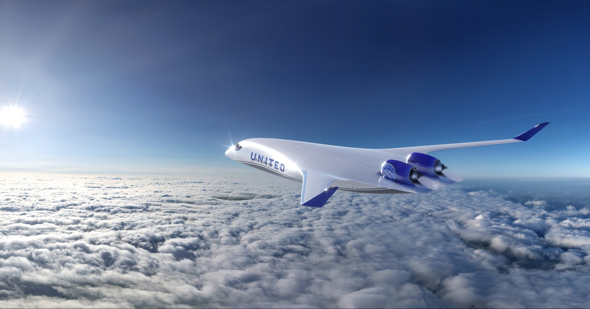
Figure 1. The JetZero Z4 BWB in United’s colors. Source: JetZero.
As the search for lower fuel consumption and emissions intensified, the search for a more efficient way to transport passengers has led to increased interest in the BWB concept since the early 1990s, primarily from NASA and the US aircraft industry.
The proliferation of composite primary structures since 2000 has helped address the structural problems of a BWB. This has created a renewed interest in BWBs, both for military and commercial applications.
The fundamentals of Blended Wing Bodies, BWBs
In this Corner series, we will look into the fundamentals of the BWB as a commercial airliner and analyze its advantages and disadvantages. To do this, we need to cover some aircraft design fundamentals, as there are many misconceptions about why BWBs would be a more efficient way to transport passengers than our dominant Tube-and-Wing aircraft.
It’s not about more lift
Much of what is written about BWB says these are good because the entire aircraft now generates lift. An airliner that cruises does not need much lift. It only needs enough lift to compensate for the aircraft’s weight, Figure 2.
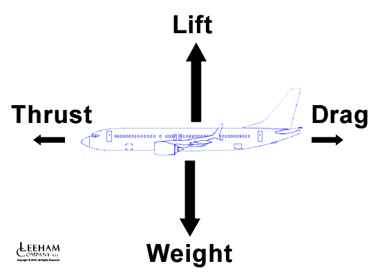
Figure 2. The fundamental forces on an aircraft at cruise. Source: Leeham Co.
The wings of Tube-and-Wing airliners do this just fine; in fact, they’re over-dimensioned for the required cruise lift. And that the fuselage of an aircraft shall generate lift is not a desired state. In fact, the advanced wings of the Boeing 787 and Airbus A350 are designed to allow the fuselages to fly with minimized lift, thereby increasing aircraft efficiency.
The micro-adjustable flaps ensure the wing curves more when the aircraft is heavy, generating the needed increase in wing lift, thereby allowing the fuselage to remain at a very low Angle of Attack to minimize detrimental lift.
To generate lift efficiently, we want a very wide structure to reduce the global circulation around it that generates induced drag (Figure 3).
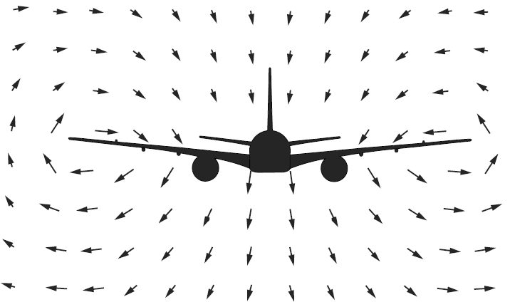
Figure 3. The global circulation that causes induced drag. Source: Leeham Co.
A fuselage is narrow and long; therefore, it is a lousy lifting surface, which creates a lot of induced drag as the angle of attack increases.
It’s about lower drag
The principal advantage of the BWB is that it can generate less drag at the same transported payload than a tube and wing aircraft. To understand how, let’s examine the buildup of drag on a typical airliner, Figure 4.
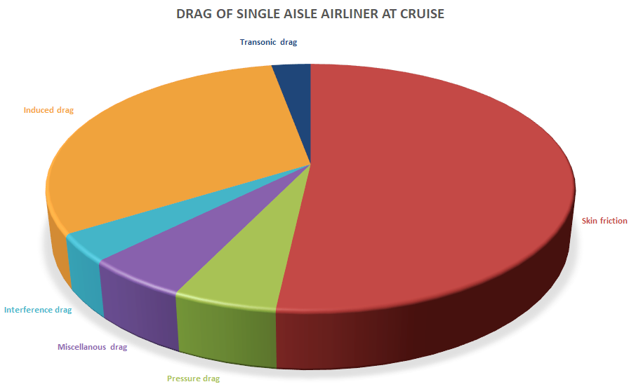
Figure 4. The drag components of a single-aisle airliner at cruise. Source: Leeham Co.
The pie chart shows the different types of drag and their size of total drag for a single-aisle airliner at cruise. The pie chart will look slightly different for a BWB airliner, but it won’t change much. What’s interesting is whether the total drag, i.e., the total size of the pie chart, can be reduced.
We see that the dominant drag for an airliner is skin friction drag, which arises on the aircraft’s outer surface and results from the skin’s scrubbing friction against air molecules. The way to reduce this drag is to minimize the surface area of the aircraft, called the Wetted Area.
The second-largest drag is the induced drag, the one where we want the widest possible airplane to stop air molecules from passing from below the aircraft to above it (Figure 3).
This is not a local wingtip phenomenon (like some wingtip device designers think), it’s a global movement that is still recognizable several wing-widths out from the aircraft. The way to minimize Induced drag is to make a wide wing and to have an elliptical lift distribution from wingtip to wingtip.
The rest of the drag types in the chart are small contributors for a well-designed aircraft. We will focus less on these than on the dominant drags: air-friction drag and induced drag.
The BWB drag advantage
So to make a BWB be more efficient than the typical Tube-and-Wing airliner for the same transported payload, we need to reduce air friction drag or induced drag or both.
A lot of research using CFD (Computational Fluid Dynamics) modelling and scale tests in small and large wind tunnels (i.e., free-air) has quantified the drag advantages of the BWB. The results vary greatly as the BWB has some fundamental problems away from cruise that can sabotage the design of an efficient BWB.
We will start detailing all this in the next Corner, now that we have established the basics of how we can achieve BWB efficiency.
The min surface area for max internal volume is a sphere. The aero of a sphere is not ideal at airline speeds. The possibility of a BWB for pax is that you can structurally make the cabin wide with carbon fibre webs inside the pax compartment to work more like a tube structure and reduce skin stresses.
Still it is easier to keep the wing+fuselage structure and get 15-20% better fuel consumption from the engines than breaking your budget/time to certification on a BWB that can give you a 5% fuel reduction. The main reason for BWB is stealth in military applications like NGAS.
current airliners provide quite a bit of load alleviation via wing bending. This requires that the main mass is separated from the lifting force via elastic elements ( here : bendy wings )
would this work on a BWB?
The wing does all the lift except at rotation where the body and nacelle helps with lift as a function of alfa at increased drag penalty. If you design wrong and need the extra lift from the body as on the MD-11 at cruising altitude. The MD-11 had other problems, at rotation dumping a little amount of condensation water on one seat in first class. The is a story that JAL got annoyed by this and placed the McDonell Douglas CEO wife in this seat on their return trip. As condensation water splashed onto her dress at rotation her husband next to her got “his fishes warm” and soon the modification came.
LOL, great story!
Bjorn, this is an excellent idea for a series. Can’t wait to read more.
Bjorn.
The infrastructure at airports is span constrained. It may be difficult for a bwb to integrate into the system if the span assoxiatedbwith a 737/ A320 replacement cannot operate out of the existing gate structure. It must occupy the same gate class anð have ground handling manners to not requirenspecial operation considerations on the ground…. Id love to hear your thoughts on this aspect.of the concept
Yes, this is one of the many problematic aspects of a BWB airliner. We will handle it as part of the series.
Folding wing?
They have the option to go down in MTOW and range so a smaller wing and PW1100G engines would do fine and still carry 250 pax JFK-ORD, JFK-MIA. So 2200nm range covers alot of US domestic volume routes. For UAL flying it from Chicago to all US volume routes would be logical if Jetzero can certify and beat the A321neo economics by 12-18%.
“as passengers would feel as if they were being transported in a coffin within the wing.”
Not a given. See Junkers G.38 : seating in the wing nose
probably problematic under safety aspects.
I believe this whole meme is waaaay overemphasized.
firstly, the vast majority of window shades are down for the duration of the flight these days, even most dedicated window seat folks don’t want the window shade up.
secondly, replacing windows with screens with passenger selectable camera angles (and properly aligned with each seat row) is both lighter and would provide a better passenger experience, as well as mitigating the window seat without a window problem.
Very interesting about the BWB possibly reducing induced
drag.
I learned more about BW vs TW in this presentation than I had in all the years I had been reading about it.
One item that sort of jumped out for me was how you differential a BW from a Flying Wing?
The other one goes back as a question for a long time and that is pax windows on an aircraft. None of this is inteded as arugmentavie and just a question if the area has really been understood.
1. Obviously we fly in the dark and you can not see much of anything as a Pax. People seem good with that. Trains as well as aircraft.
2. These days, getting on an airplane in daylight, half the widow passengers pull the shaded down. Agreed that is not all etc, but do people realy want to look out or do they take a window seat so they can lean against the side and sleep? (playtime).
3. Are windows just previous form of distraction/entertainment while traveling to help the bored factor? Ergo, replaced with smart phones, panels in front of the pax on the seat back and maybe we don’t need windows? Screen could have a camera mode if you want to look out.
the whole no windows thing is way overblown. as you say most folks pull down the shade the second they get in the plane.
replacing windows with screens that can be tuned to multiple camera angles is lighter & more structurally efficient and provides an overall better customer experience.
additionally it would fix the poorly aligned window issue and the no window issue.
Completely forgotten is the UKs Armstrong Whitworth ( part of Hawker Siddeley then) major flying wing development program from 1944 to the mid 1950s which was, unlike Northrop, leading to a possible commercial aircraft design
A.W.50 Concept The initial design for the scale test aircraft.
A.W.52G Glider A 53 ft 10 in (16.4 m) wooden glider built to test low-speed handling. It first flew on 2 March 1945, towed by a Whitley bomber.
A.W.52 (TS363) 1st Prototype Powered by two Rolls-Royce Nene engines (5,000 lbf each). It first flew in November 1947 but was lost in a 1949 crash due to severe pitch oscillation.
A.W.52 (TS368) 2nd Prototype Powered by two lower-powered Rolls-Royce Derwent engines (3,500 lbf each). It first flew in September 1948 and continued research at the RAE until 1954.
Proposed Commercial Airliner. A six-engine, 180,000 lb airliner design with a 160 ft wingspan. Never got off drawing board concept phase after above test trials failed to maintain laminar flow. A V bomber version AW56 had more detail
thanks, rather interesting (commentary):
https://www.flugrevue.de/klassiker/armstrong-whitworth-a-w-52-britisches-nurfluegler-experiment/
I always thought that the main issue (apart from gate) is emergency egress. Hoping that this will be covered here.
I’m looking forward to your takeoff and landing analysis.
With the small distance between the landing gear and longitudinal control surfaces and the relatively long distance between the cg and the landing gear may mean the high lift system will need to be very simple.
This may force more wing area into the configuration for acceptable low speed performance by requiring additional wing area. That will not help the BWB wetted area disadvantage.
The high vertical engine location won’t help either.