Leeham News and Analysis
There's more to real news than a news release.

 Leeham News and Analysis
- GE testing of giant GE9X engine aims for maturity at entry into service June 30, 2025
- Bjorn’s Corner: Air Transport’s route to 2050. Part 28. June 27, 2025
- Parent agency, FAA often at odds as politics outweighs safety June 26, 2025
- Electric Flight and the Ugly Duckling June 25, 2025
- Engine makers tout “Plan A” but have “Plan B” backups in R&D June 23, 2025
Bjorn’s Corner: Fly by steel or electrical wire, Part 12
October 11, 2019, ©. Leeham News: In our series about classical flight controls (“fly by steel wire”) and Fly-By-Wire (FBW or “fly by electrical wire”) we continue our discussion of pitch stability augmentation systems when we have a mechanical (“fly by steel wire”) pitch control system.
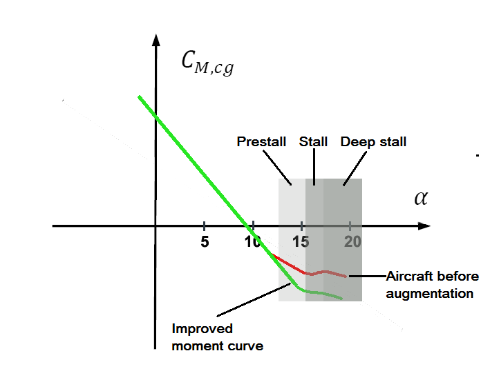
Figure 1. The typical pitch moment curve of a modern airliner. Source: Leeham Co.
Pitch stability augmentation with a mechanical base system
In last week’s Corner we went through the flight cases when a pitch augmentation is necessary if the base aircraft has a pitch moment curve like in Figure 1.
We concluded:
- The problem is limited to a clean aircraft in the case we study. For our reference case, the 737 MAX, a stability augmentation is not needed when the slats/flaps are deployed (the slats stops the flow change which transfers the center of lift forward at high Angle of Attack (AoA).
- At high speed we have high horizontal tailplane and elevator authority, at a low speed we need large movements of these surfaces to counter pitch up problems as the authority is low.
- It’s hard to find flight situations where the pilots would need to fly the airliner in the region of reduced stability. There are theoretical cases and these must be addressed for the aircraft to be certified as safe in all cases but practical situations are hard to find. The most probable case seems to be a botched circling when we fly slowly with a clean aircraft (remember the case shall involve a clean aircraft).
Tools for implementing a pitch argumentation
With feedback based FBW we have the perfect tools to fix problems like the reduced stability region in Figure 1. The aircraft measures its behavior and auto-corrects any misbehavior. It has flexible and powerful tools to do this and system redundancy to allow these tools to be active in the needed cases are there.
For an mechanical flight control system, it’s harder. We discussed how any gearing ratio change (giving a control surface deflection ratio changes) based on for example flight speed is difficult to achieve. But we need different deflections of control surfaces at low and high speeds as the dynamic pressure, Q, which gives us the control forces, changes.
Further, if we use the normal pitch channel which controls the elevator to get these forces, we take away elevator authority from the pilot which he might need in an emergency or when countering an augmentation system gone awry.
If we can’t use the elevator we soon land on using the horizontal stabilizer trim system for our augmentation.
One could argue we should find a base aircraft solution to the problem, like an aerodynamic fix. Such a fix would probably look like the ventral fins on the underside of the aft fuselage of a Learjet or on a Boeing 737 Wedgetail. But these fixes are there at all times, costing weight and drag and by it, fuel consumption in normal flying.
As discussed the flying in this pitch AoA domain is very improbable. An airline pilot should not have been there in his career. The installation of an aerodynamic fix is, therefore, not optimal if it degrades efficiency in normal flying. If we can devise a fix that goes active if needed but is not present when not needed it’s better.
So we soon end up with the trimming of the horizontal stabilizer as our tool. It’s a tool that is free for use in manual flight as it’s so powerful the pilot will not use all its authority to trim the aircraft in his manual flying.
What we need from the horizontal stabilizer trim system
We will detail what we need from the trim system in this Corner, then we discuss how to achieve these needs in the next Corner.
We need:
- A system that is highly reliable. When it’s needed it should be there when not the probability of misbehavior shall be extremely low.
- We need a system that can move a small distance with a low slew rate at high aircraft speed (Q is high) and can move a larger distance with a higher slew rate at a lower speed when Q is low.
- As the authority of a horizontal stabilator trim system is large we need a reliable trigger for when it shall go in action and when it shouldn’t.
- We also need a system where its failure modes shall not create forces on the aircraft which are hazardous, neither for control of the aircraft nor for its structural integrity.
- Because of the power of the horizontal stabilator we need a system that can be limited in its authority. The pilot must always be able to mitigate any failure of the system with his elevator.
With the requirements outlined above, we will in the next Corner discuss how we can implement such a system, what components fulfill our needs and what trade-offs we will have to make.
Bjorn, I understand that various aerodynamic fixes were explored, and rejected in favour of MCAS, and you have explained why this would be the case.
Regarding the pitch moment curve, I saw a post saying that apart from making the control column ‘lighter’ to pull back as high AOA is reached, it was also harder to push the control column forward to reduce the AOA, this does explain why the horizontal stabiliser was used to counter this tendency.
I do wonder about the vortex generators, BA removed them from the aft fuselage with the re-design, but apart from the engine mounting, and the new scimitar winglets, just how much has the wing has changed from NG to MAX, are there vortex generators present on the MAX wing ?
For anyone not familiar with vortex generators, there’s a very good visual demonstration of what they can do here https://www.youtube.com/watch?v=SXwVyxorvno
and explained simply here https://www.boldmethod.com/learn-to-fly/aerodynamics/vortex-generators/
Perhaps BA should have used ventral fins that pop-out, or fold down from the fuselage as high AOA is approached, but of course that would be very visible, and would have raised questions as to why it was necessary !
I’ve only recently noticed the forest of vortex generators on the back of the NG, are they tackling similar issues or something else?
Grubbie you also see VGs on the nose of the BG ( MAX as well I think) under the windows, to reduce noise apparently.
http://www.b737.org.uk/fuselage.htm#EYEBROW_WINDOWS
Aft body vortex generators – http://www.b737.org.uk/fuselage.htm
I’m more interested in VGs on wings due to the effect they have on stall speed.
To all,
regarding vortex generators. The ones of the back of the NG is reactivating a boundary layer that has let go and this creates drag caused by the turbulent flow which then develops. So these VGs are there to make the flow attach better around the rear fuselage. This disturbed flow causes drag but don’t contribute to the pitch up at high AoAs. The ones on the wings of Boeing aircraft are most often to stop a local transonic flow-induced pitch up tendency when flying close to the max Mach. It has nothing to do with MCAS or high AoAs.
Any movable vane on the rear fuselage has its own problems. What if the vane gets stuck, you’d have to have contingencies for it and cautions etc. Movable aerodynamic fixes are to be avoided, they open their own can of worms.
Thank you Bjorn.
The MAX lesson seems to be that it’s problematic to add partial FBW to a “fly by steel wire” aircraft. Either do the FBW implementation extremely well, or rely on the aerodynamics, and classic “fly by steel wire”, don’t try to cut corners !
You repeatedly wrap something in another layer of faked paradigms. One over the other.
Obviously that will produce collisions at some point when expectations from the outer presentation “persona” cannot be met by the inner layers.
Here the gimmicks present the immitation of a sane aircraft design on the surface. If you scratch the surface you get kind of a Werewolf transformation in your face.
JD:
I think the lesson is, do it right, not fly by night Mother Jones barnstorming company designs with baling wire and bubble gum.
RE transworld
” welcome to the grace l ferguson airline and storm door company ” Bob newhart
But if one goes to the RED BARN ( Seattle museaumm of flight ) which is the origional Boeing company building, upstairs you will find a dioarma of the Friday harbor storm door company women sewing fabric on the wings of the early boeing planes ”
https://www.museumofflight.org/Plan-Your-Visit/Private-Events/Event-Spaces/Red-Barn.aspx
Hi JackDak. The Lockheed SR-71 Blackbird (1950s technology) had a ‘steal’ mechanical hydraulically system in which Pitch, Roll and Yaw stabilisation and augmentation was added in mechanically. The mechanism for trimming in the computer input could be a differential gearbox or more likely a lever mechanism in which the fulcrum point can be moved by a servo to trim in the computer input. Could Boeing have added the MCAS function to the elevator (instead of the Stabiliser) in this way, aftercall they were already doing this with the yaw damper on the rudder. There is some discussion as to whether the stabiliser was used instead of the elevator because elevator simply lacked the authority.
Thanks for a great explanation.
However, your particular argument against using the elevator channel is less than convincing.
In a pitch-stable airframe there is no stall without pilot input. Stick pushers are around since decades. Stick pushers are designed to be overridden manually in case of malfunction. They do not effectively reduce pilot pitch authority, they just remind the PF forcibly to stop pitching up.
This leaves us with the Finding F3.4-A raised by the JATR committee: The acceptability of the natural stalling characteristics of the
aircraft should form the basis for the design and certification of augmentation
functions
BR
Albrecht