Leeham News and Analysis
There's more to real news than a news release.


Bjorn’s Corner: Air Transport’s route to 2050. Part 13.

By Bjorn Fehrm.
March 14, 2025, ©. Leeham News: We do a Corner series about the state of developments to replace or improve hydrocarbon propulsion concepts for Air Transport. We try to understand why development has been slow.
Last week, we summarized the well-to-use efficiency gain of the Pratt & Whitney HySIITE engine process, which was announced in January. We found that with an expected 35% increase in engine efficiency, the liquid hydrogen chain, from the splitting of water into hydrogen and oxygen through liquefaction to burning it in the engine, used less renewable energy than if we used the same method to make Power to Liquid (PtL) SAF.
Pratt & Whitney was very clear in the presentation that the evolution of a HySIITE engine is a long-term project, with its possible use on the other side of 2040. There are just too many new components (heat exchangers, evaporators, etc.) that need development and maturation to think this is a near-term engine opportunity.
MTU’s similar WET engine concept, Figure 1, uses the same process ideas but with a different target. Here, the focus has been reducing emissions, like NOx and water content in the exhaust, to reduce contrail risk. This shall be achieved when burning jet fuel, SAF, and hydrogen.
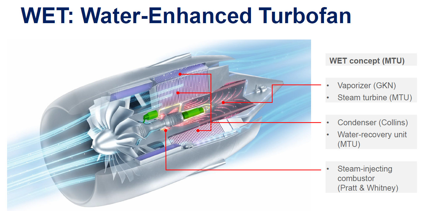
Figure 1. An MTU WET engine with its straight core. Source: MTU.
The WET engine concept and characteristics
MTU and later its partner DLR (Germany’s NASA) chose a straight layout (Figure 2) instead of the backflow core that HySIITE chose. This layout places large components like the evaporator and condenser at the back of the engine.
The capture of the water from the engine exhaust follows the same process as for HySIITE. The exhaust first passes the evaporator, where the injection of the captured water boils into superheated steam. The steam is then routed to the entry of the combustor and injected there to form a steam and air mix that oxidizes the fuel.
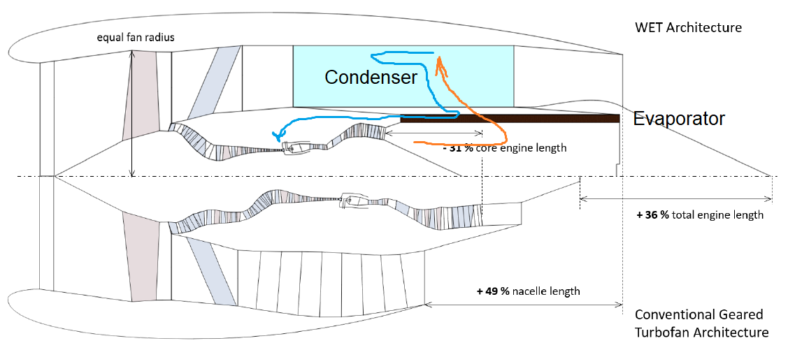
Figure 2. The WET engine’s flow of exhaust and its capture of water. Source: DLR
The effect, the control of the burn process to lower NOx and the increase of the turbines’ power, is the same as for HySIITE. The increase in turbine efficiency allows a reduction of the core size. It can now drive a fan with BPR 28 instead of 13 for the Pratt & Whitney PW1100G for the same-diameter engine.
As the oxidation of Kersosene with ambient air generates 2.8 times less water than when burning hydrogen, the core’s efficiency increase is less than for HySIITE. When DLR sums up the pluses and minuses of the WET in two conference papers from September last year, there is not the clear benefit from the process that we saw for HySIITE.
These papers do not provide a direct fuel burn reduction, but earlier work by MTU has mentioned a 10% to 15% efficiency improvement from a WET engine compared with a standard PW1100G.
The DLR papers detailed the negative of a WET engine compared with the PW1100G. The engine and nacelle would be 36% longer, and it would be 84% heavier due to the added evaporators, condensers, and ducting. This is when using a, in my opinion, less efficient straight core arrangement. An inverse core like the HySIITE would be more natural when the core shrinks as much as for these engines, and the architecture demands large evaporators and condensers.
DLR also found that the engine’s pressure ratio would be limited, as the last compressor stage in the axial compressor would be too small for a higher compressor ratio than 30 (tip losses increase when the blades go below 10mm in length).
This is a strange statement, as when the cores get smaller, you change to a radial stage, replacing the last axial stages, to avoid the tip losses of a narrow axial stage. This is standard practice for all small core engines, such as executive jet turbofans or helicopter engines.
The WET engine’s future
Overall, I find DLR’s investigation of the WET engine to be focused on the emission side, with some study choices and limitations that constrained the concept’s efficiency potential. However, with 2.8 times less water in the combustion gases, this cycle’s added complexity might not be worth it anyway. And there are more straightforward ways to control contrails. We will cover this in a later Corner.
The MTU CEO, Lars Wagner, shall have answered in their 2024 results press conference in February that the WET concept is not pursued for the next-generation engine work together with Pratt & Whitney. This is natural, such added complication to an engine is not something that one develops from one generaton to another. And it’s questionable if such complexity is worth it for an engine that burns kerosene.
At Boeing, we did a water misting injection study with NASA funding and found injecting water prior to the compressor improved engine fuel efficiency (like the GE Sprint) but injecting it directly into the combustor resulted in lower TIT and therefore lower fuel efficiency.
With the inject of water that lowering of efficiency seems consistent with other experiences hence the use of steam / water that has been heated with recovered waste heat.
Putting water into the combustor is mainly to increase power thru higher fuel flow to reach the same Turbine inlet temp (because you cool the compressor exit airflow and the stream forming energy) and increased massflow thru the turbines that causes more shaft power. In the old days the USAF would buy and go thru the “bleeding edge” of this hydrogen technology before commercial applications.
Water methanol injection into olden-days turbojets and turboprops didn’t put it into the combustor but the compressor.
The idea (which worked) was that the cooling of the air in the compressor made subsequent compression in later stages require less work from the turbine. Thus more thrust was available.
I never saw mention of it improving the engine’s efficiency (as opposed to thrust, which it certainly did).
If you see pictures of a B47 or early B52 take-off there’s an alarming amount of smoke by modern day standards. I understand that this was because the water (which would have been steam by the time it reached the combustor) quenched the flame somewhat and led to dirty combustion.
I still don’t understand how contrails are reduced.
Also, I still wonder why a condensor/evaporator which doesn’t produce any power is a better source of water than a fuel-cell which does (and doesn’t need to be anywhere near the engine).
With regard to contrail formation, I assume that my understanding must be incorrect?
“ The traditional exhaust flow due to its relatively high temperature will have the water in a vapor state which when cooled will produce a fog of very extremely small particles and hence a significant contrail (obviously using hydrogen will produce a larger contrail). With a HySIITE / WET style of turbine engine the condensation of some / all of the water from the core exhaust flow generates water (or at least forms significantly larger water droplets). The excess water / water droplets that are ejected from the aircraft are more like rain droplets than fog and hence the curtailed contrails. The pseudo-GHG effect of contrails seems to be dependent upon droplet size.”
With regard to using the water / water vapor output of a fuel cell, does that reclaim any waste heat or provide enough water?
Normally you need soot particles that the cooled steam can condensate onto, if no particles there is uncertianty on how much condensation will happen. Like burning pure hydrogen produces no soot, so there will be flight trails to measure what happens.
I guess you are referring to the PERSISTENT contrails that can form in very cold and humid air called Ice Super Saturated Regions (that are associated with soot particles and preexisting atmospheric particulate) vs the contrails associated directly with the exhaust of the turbine. It is suggested that the hydrogen-fueled engines should produce larger ice crystals (and obviously no soot), which will more quickly drop out of the atmosphere. The HySIITE style of engine significantly increases the size of the water droplets even further (and correspondingly lowers the number of ice crystals), which should produce much larger ice crystals that drop out of the higher atmosphere even faster.
I am very interested in reading the later Bjorn’s Corner that will talk about contrails. I am particularly interested in the EU perspective on these general topics as the U.S. appears to have little to contribute from a scientific or political standpoint.
Results from flight tests will come: https://www.airbus.com/en/newsroom/press-releases/2022-02-airbus-and-cfm-international-to-pioneer-hydrogen-combustion
With regard to Airbus and hydrogen fuel generated contrails, it is probably the Blue Condor test program that will find these answers. Blue Condor is an experiment by Airbus and DLR (the German Aerospace Center). Scientists plan to measure the composition, including the size of the ice crystals, of the contrails left by hydrogen combustion. The A-380 aircraft wasn’t useful for the contrail experiment because pristine atmospheric air is needed (one not contaminated by the conventional fueled engines).
“There are no contrail data available from hydrogen combustion, so this is really a first, and therefore it’s extremely exciting for us,” says Tina Jurkat-Witschas, head of the DLR team.
IMU:
the condenser retrieves energy of evaporation
and thus heats bypass massflow slightly, providing a thrust increase.
water in the combustor replaces nitrogen reducing the chance for NOx creation. ( compare “condensing boilers” in household heating apps.)
Q: Does water injection reduce OPR?
It is interesting that you mentioned “as when the cores get smaller, you change to a radial stage, replacing the last axial stages, to avoid the tip losses of a narrow axial stage.”
MAN Energy Solutions’ AR-MAX1 Axial-Radial Flow Compressor (86,000 horsepower input to the compressor) is a truly massive beast of a compressor. It is interesting that even an extremely large diameter compressor used the same strategy of 6 axial stages, intercooler, and then a relatively compact radial stage. Since this is a recently developed compressor, it is clear that this axial to radial design concept must have additional advantages. Obviously, this is a ground-based system, and size and weight are not a direct consideration; it must also be the more energy-efficient configuration.
Intriguingly, a comment was made by the manufacturer at the presentation ceremony that many of the customer participants were from companies that were looking into E-Fuel / synthetic fuel production. Another sort of connect-the-dots moment with regard to what it takes to move to a low-carbon fuel production model.
Wasn’t there an engine and airframe program cancelled because that last stage axial compressor did not work on a larger engine?
Are you referring to the last centrifuge stage in the Safran Silvercrest engine for the Cessna Citation Hemisphere?
YES
Sorry for the previous abrupt reply. Thanks for the detailed information. There was much discussion about this on the main blog when it happened. The general tone was that experienced engine people should have known better than to attempt this.
Think it was the transients that killed this engine as the large inertia of the radial compressor would need matching large bleed valves. Shound not be so difficult to design for a stationary gas turbine running at max continious power.
Hi Ron.
Is there a link to where this is discussed?
Cheers Gerard
From my googling, the engine’s problems were not due to the last stage radial compressor but due to issues in the HP axial stages upstream of the radial / centrifuge section. Some references go out of their way to explicitly state that. But personally I think that one can assume that the designing of the axial stages were complicated by the radial section.
It is interesting to go down the rabbit hole of relative efficiency and generally the overall efficiency of axial compressors is around 5% better. But if one looks at it from a per-stage efficiency as the diameter gets smaller where the axial efficiency per stage decreases due to tip tolerances ( etc ) it is understandable why the choice was made.
The airplane in question was the follow-on to the Textron Latitude and Longitude.
I can see experimenting in both configurations, you always learn something.
MTU and P&W are basically in a joint venture with the Japanese engine companies on GTF so that work is all going to get pooled. Its IAE with P&W the listed lead but the others all have major parts involvement.
They will learn things that can get inserted into the GTF current or the next Gen GTF.
Sorry for the previous abrupt reply. Thanks for the detailed information. There was much discussion about this on the main blog when it happened. The general tone was that experienced engine people should have known better than to attempt this.
I think you are posting on the wrong subject in the wrong place.
Engine discussion, future engine and not on any airframe, purely a test or experimental engine not intended to be put into service.