Leeham News and Analysis
There's more to real news than a news release.


Bjorn’s Corner: Blended Wing Body Airliners. Part 4

By Bjorn Fehrm
April 3, 2026, ©. Leeham News: We have started a series of articles on the Blended Wing Body (BWB) as a potentially more efficient design for passenger-carrying airliners than the classical Tube And Wing (TAW) configuration.
In the third article last week, we saw that the large wing surface area of a Blended Wing Body does not come from cruise-phase requirements; it comes from the lift needed in the landing phase, where BWBs lack flaps to increase wing lift. It needs a large wing area to compensate.
Now we will see that the wingspan does not come from cruise requirements, but from takeoff requirements.
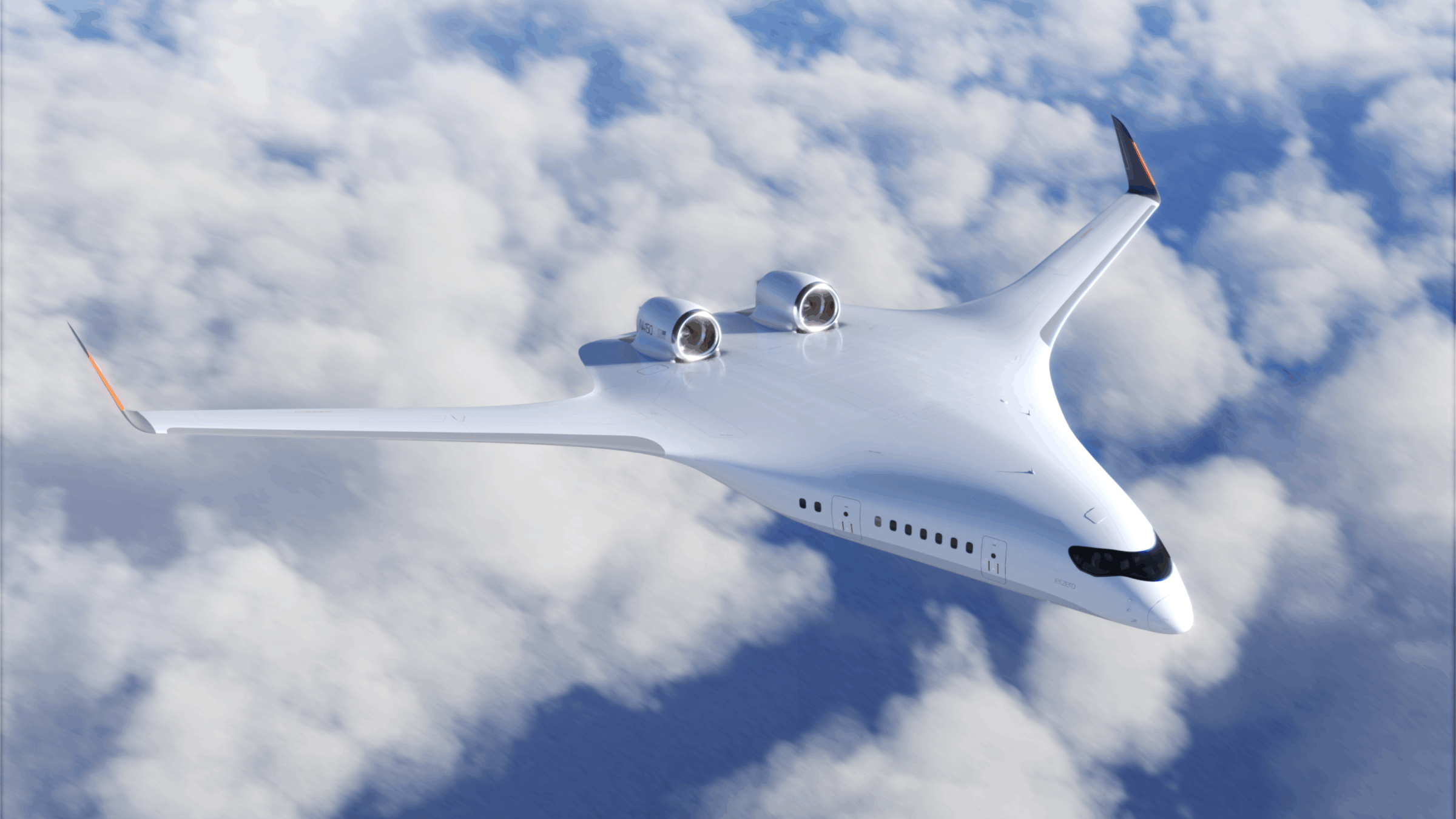
Figure 1. The JetZero Z4 BWB. Source: JetZero.
The Takeoff Sizes the Wingspan of an Airliner
Before starting this series about BWBs, I read through more than 10 reports about the aerodynamics and structure of BWBs. None of the reports I found examined the takeoff and landing performance of BWBs; they all focused on the cruise phase, comparing the efficiency of the BWB and the Tube-And-Wing airliner.
This is surprising, as several critical parts of a BWB are determined by regulatory and operational requirements around airport operations. It’s the most dangerous part of a flight, where most accidents occur. It’s why there are very strict and demanding requirements around takeoff and landing performance, both from a regulatory point of view and from airlines when they acquire an airliner.
We all know the bad safety reputation of the McDonnell Douglas MD-11 (I will not call it Boeing because Boeing didn’t design or certify it). The MD-11’s root problem is high approach and landing speeds, coupled with structural design problems around the engine installation. The MD-11 passed certification, but its practical performance was too demanding, and the conditions and pilot skill spread led to it having more than its share of accidents around the airport.
The BWB might have advantages in an optimized cruise (we will come to why I write optimized), but its challenges are around the airport. We have handled the approach and landing; now we turn to takeoff, and why this is a sizing factor for the wingspan.
The Takeoff is an Induced Drag Problem
Few people I ask know the role of induced drag in an aircraft’s takeoff. It’s 85%-90% of the problem. The simple graph in Figure 2 explains why. It tells a deeper story than a first glance suggests.

Figure 2. The main drag components of an aircraft and how they’re affected by airspeed. Source: Leeham Co.
The figure shows the main components of an aircraft’s drag at subsonic speeds. The parasitic drag is dominated by air-friction drag and can be referred to as drag due to size. Induced drag, which is the circulation around the wingtips, can be called drag due to weight. There is also supersonic flow drag, or wave drag, but at airliner speeds it is below 3% of total drag.
The graph in Figure 2 shows the following;
- The lowest total drag is at the point where the Parasitic and Induced drag are equal in size.
- At low airspeed, the induced drag is the dominant drag component.
- At high airspeed, the parasitic drag is the dominant drag component.
- What is not shown by ease to understand is that as air gets less dense with altitude, the drag due to skin friction reduces (fewer air molecules rub against the aircraft skin), and the induced drag increases as the wings work in less dense air, increasing the wingtip circulation.
Points 1 and 4 state that an airliner shall be flown at a speed and altitude at which it can find the point of minimum drag.
Point 2 says that we have a high induced drag at takeoff and landing.
Point 3 tells us why airliner designers minimize the size of an aircraft’s different parts, to have the lowest wetted area possible.
The critical part of an airliner’s takeoff is not the normal takeoff when both engines are working. Aircraft regulations focus on required performance when things go wrong. In the case of takeoff, it’s when an engine fails after the aircraft rotates and starts the climb after Vr in Figure 3.
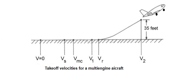
Figure 3. The takeoff run speeds. Source: Aerospaceweb and Leeham Co.
For a twin-engine airliner, the regulatory requirement is that it shall be able to climb at 35ft height after rotation at 2.4% climb rate, i.e., 2.4m for every 100m traveled, without losing speed. The V2 speed is close to the Vr speed, which is past V1, where the pilots shall stay down and brake. The Vr and V2 points define the runway length, so airliner designers must keep these speeds as low as possible. (The Vs is the stall speed in takeoff configuration with both engines running; Vmc is the lowest speed at which the pilots can aerodynamically control the aircraft if an engine fails).
Keeping V2 low to enable the airliner to use many of the world’s runways is a tough certification point, as we are now down to one engine, and that engine has lost thrust due to thrust speed lapse. At a V2 speed, which is typically past 100kts, we have lost about 15% of static thrust.
The thrust we have left on the one engine shall overcome aircraft drag and enable the climb angle of 2.4%. Induced drag is now 85% to 90% of total drag (skin friction drag is low as we are flying at just over 100kts).
The V2 case is a key determinant of an aircraft’s wingspan and wingtip types. When the Boeing 737 MAX got split wingtips, everyone focused on what it would save in cruise fuel burn for the mission. Boeing was as focused on how it would affect the LEAP-1B engine sizing for the aircraft. A lower thrust engine, driven by an improved V2 situation, enabling a lower engine maximum thrust range that benefited the overall economics of the MAX series.
For our BWBs, the Z4 with its Pratt & Whitney 2040 engines has a wingspan that is tight against the class E border of 55m, the same as the much heavier 315-seat Airbus A350-900 or 365-seat Boeing 777-300ER. But its engines are less than half the thrust of these two.
The Z4 wingspan is clearly sized by the takeoff V2 case. The climb and cruise of the Z4 would have benefited from a lower wingspan, which would have reduced the wetted area and found an optimum drag point at a lower altitude than is the case with the 55m wing. We will see later in the series that the Z4 has a very unbalanced cruise combination of skin-friction and induced drag, which forces a very high cruise altitude range (case 4 in Figure 2), creating problems with engine selection.
When I attended the March 21 meeting of the Pacific Northwest chapter of AIAA (American Institute of Aeronautics and Astronautics), I spoke on the sidelines with four Boeing engineers. Three are retired and one is currently employed. None believe the BWB is a viable alternative to the tube-and-wing aircraft. Three specifically pointed to the drag issues Bjorn describes above. The fourth was more general in his comments, as the meeting was beginning and we ran out of time.
Years ago, Mike Sinnett, who headed product development at the time, appeared as the speaker at the University of Washington Aerospace Department. On the sidelines after the meeting, he told me that he, too, is not a fan of the BWB. His objections centered around the challenges of making a family of airplanes for a reasonable cost and for fitting the airplanes within current gate space at airports. His was a particularly interesting set of comments because Sinnett came to Boeing with the McDonnell Douglas Corp merger, and it was an MDC engineer who first came up with the BWB passenger airplane design.