Leeham News and Analysis
There's more to real news than a news release.

Bjorn’s Corner: Aircraft drag reduction, Part 19
 February 23, 2018, ©. Leeham Co: In the last Corner we wrapped up the discussion on different drag types by discussing some less dominant drags.
To finish the series we will go through a typical mission for an airliner and study which drag is important when and why.
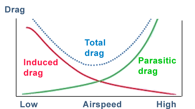
Figure 1. An aircraft’s drag profile as airspeed varies. The main part of Parasitic drag is air friction drag Source: Leeham Co.
Drag of an Airbus A320
To be concrete, we will look at how the drags vary when an Airbus A320 flies a typical 800nm route. We assume our aircraft is the A320neo type with a cabin with 180 seats, all filled with passengers.
Take-Off
Our aircraft will have a Take-Off Weight of 60t for the flight. This weight will be the source of our induced drag. The aircraft’s wetted area (the surface which touches the air) of ~800m2 will cause the air friction drag.
At our take-off roll, we have minor air friction drag as the speed is low. On average it will be around 1.4klbf (6kN) during the ground roll. Our engines develop 27klbf (120kN) each at first, which gradually declines to around 22klbf (98kN) at rotation speed because of forward speed thrust lapse (the ejected engine air’s overspeed versus the surrounding air declines as the aircraft speeds up).
The major force the combined 54klbf engine thrust (declining to 44klbf) have to fight is the wheel roll drag, which on average will be around 17klbf for the roll. What is left of engine thrust when the air friction and wheel roll drag is counted, is used to accelerate the aircraft to its rotation speed of 130kts.
Once we rotate, the induced drag of the aircraft shoots up (Figure 1). We have low speed; therefore, the air friction drag is low, less than 3000lbf. But our induced drag is high, 8,000lbf.
Taken together, the total drag is 11,000klbf. Our engine thrust is now 21klbf per engine. We only need around 16klbf of engine thrust to manage the regulatory 2.4% climb, should one engine fail. Therefore, airlines use engine derate if they fly short sectors like the 800nm route we are flying.
Climb
Our initial flight level would be FL370 with the rather light A320neo if we would use the full climb power of the engines (a climb derate would probably be used by an airline).
Our initial climb would be at 250kts, as we would be bound by the highest allowed airspeed under 10,000ft. This speed restriction is used to have all aircraft manoeuvring around the airport at the same speed.
At 250kts our friction drag would be around 4,500lbf and our induced drag ~3,500lbf. Our induced drag is low for our airspeed of 250kts. It’s because the air is fairly thick below 10,000ft (it has high density).
When we speed up to 350kts after having passed 10,000ft and gradually meet our climb Mach of 0.76 at around FL300, we have an air friction drag of around 7,000 lbf and an induced drag of 2,000lbf at 20,000ft. Our engine thrust has now declined to 8,500lbf per engine, because of less dense air and a forward speed of 350kts.
Cruise
In the next Corner, we’ll finish the mission by going to our cruise altitude and explore the drags there, followed by the descent and landing.
Thanks Bjorn. I didn’t realize that wheel drag is so high during takeoff role. If the A320 takes off at MTOW, how much higher would wheel drag be? Less than proportional to weight? For larger planes, would it increase – versus A320 – in approximate proportion to takeoff weight?
Your mention of rotation also has me wondering something about the sizing of the horizontal tailplane: Is it usually sized according to rotation force/moment needed? Or is approach stability or some other constraint more common?
Hi Eric,
you can assume it’s linear, this how my model does it and I have taken the values from those who should know. Re horizontal stab, it’s sized by the lowest speed with the highest nose down moment case. Should be the flare phase when landing as the landing flaps give a higher moment (and more drag) and the flare speed at MLW could be lower or at least close to the rotation speed for a light aircraft.
Hi Bjorn
Is there a benefit for using a clean wing design at take off and landings. A caravelle, DC 9, Tu 134, Tu154, Fokker 100 etc. design should benefit from a wing in ground effect. This should relieve the wheels and reduce wheel drag while the plane is rolling on the ground.
Clean, or at least cleaner takeoff helps indeed. Usual T/O flap settings include a so-called sealed slat position, which means that the slat will not open its gap in this Position. Same for Double-slotted flap systems: in T/O you try to have one gap closed. Opening the H/L System gaps to have the Full Lift results in a drag increase of roughly 20% versus the clean a/c friction drag.
Hi Matt,
there is a clean wing advantage for a rear-engined aircraft. You won’t have much ground effect until rotation, you run with low alfa on the wing and therefore little spanwise rotation (which the ground effect inhibits to an extent) until rotation. But the clean wing has a little higher lift at TO and landing, everything else being equal. The engine nacelles and pylons disturb the flow a bit. The engine underwing is a structurally better concept once you get a little size on the aircraft (so your landing gear sized by rotation clearance gives you space for the engines), therefore the larger aircraft take the lift penalty of engines on wing.
Thank you Bjorn
So a low mounted clean wing makes sense. even a plane has to operate from unprpared airfileds like the soviet aircraft or the new Pilatus PC24 which has a clean wing design and is especially designed for rough airfields.
Mounting engines under a low wing also has its limits. The B737 reached the limits it cannot fit larger engines with the current design. As efficiency gets more and more important the bypass ratio is going higher and higher. Means the turbofans get larger and larger. New materials in aircraft and engine manufacturing will get smaller and smaller improvements. IMHO the industry will soon reach a point where a radical new design is needed. Like blended wing bodies with counter rotating ducted fans. A bypass ratio of 50:1 should allow for a fuel burn of less than 1.5l/100km per pax. So for low range aircraft i could think of two large rear mounted engines or four smaller ones like the BAe 146 used.