Leeham News and Analysis
There's more to real news than a news release.

Bjorn’s Corner: Fly by steel or electrical wire, Part 11
October 4, 2019, ©. Leeham News: In our series about classical flight controls (“fly by steel wire”) and Fly-By-Wire (FBW or “fly by electrical wire”) we now discuss pitch stability augmentation systems when we need to improve the pitch characteristics of a mechanical (“fly by steel wire”) pitch control system.
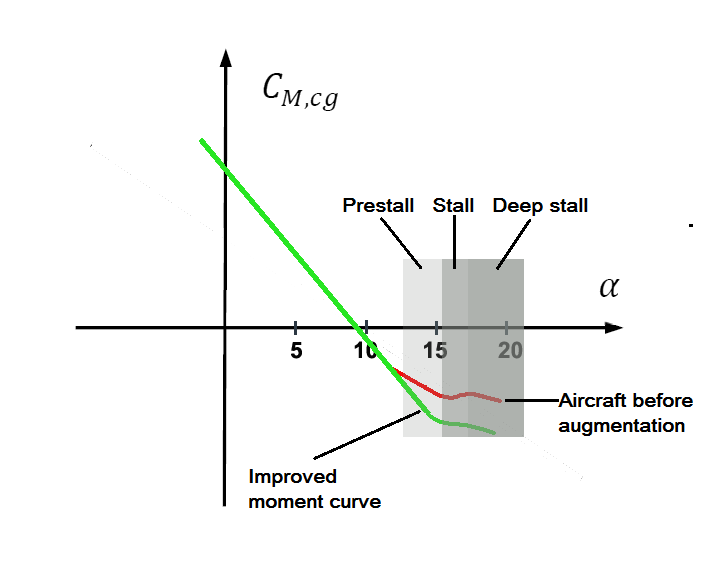
Figure 1. The pitch moment curve of a modern airliner when circling before landing. Source: Leeham Co.
Pitch moment curve augmentation with a mechanical flight control system
After covering open-loop and feedback Fly-By-Wire pitch augmentation in the last Corners we now turn to how to implement argumentation when we have a mechanical base pitch system.
We assume we have a non-linear pitch moment curve for the aircraft as shown in Figure 1. We will use the Boeing 737 MAX as an example of such an aircraft but this curve is representative for many modern airliners with large engines.
High-speed case
Let’s first examine the high-speed case, meaning we fly at speeds above those used when taking off or landing.
It’s then very hard to achieve the high Angles of Attack (AoA) where the aircraft gets nose-up happy as shown in Figure 1. To fly above 10° AoA at normal flight speeds we would need the Pilot to pull in the region of two Gs or more.
This means all passengers and cabin personnel would weigh twice their normal weight and would have problems standing up or sit straight. There would be meals and coffee all over the interior and confusion/panic would spread.
To understand how far off this is from normal flying we shall know we are subject to less than 1.2 G when we fly commercially. A normal turn for an airliner is maximum a 30° bank angle turn and this means we weigh 1.15 times our normal weight.
Airliner crews excel in flying as smooth as possible with Gs lower than 1.15 if they can for the whole flight. This is their challenge, not to fly at high AoA (and therefore high Gs). Even in evasive or brusk corrective maneuvers, it would be extreme for them to pull more than 10° AoA.
The maximum allowed Gs for an airliner before the aircraft needs a structural inspection is 2.5 G (Limit load). The aircraft is designed to keep together at up to 3.8 Gs (Ultimate load).
If we assume we make a high G maneuver at high speed to avoid hitting something or we run into the vortices from a large aircraft we might momentarily achieve Angles of Attack which could hit the region with less stability.
At these AoAs the aircraft will be nose-up happy and we feel like the aircraft pulls further G’s by itself. It digs into the maneuver. To have an easy to fly airliner we need pitch augmentation to fix this.
Low-speed case
The probability of running into the region of a nose-up happy aircraft is higher at low speeds. We must remember the pitch moment curve in Figure 1 is for a clean aircraft.
As soon as we deploy flaps the slats are deployed as well. This controls the flow over the wing so the moving forward of the center of lift which causes the loss of stability in Figure 1 doesn’t happen (it can still change the curve slightly but it didn’t require augmentation for the 737 MAX).
We don’t fly a clean aircraft until after take-off when we climb out with normal climb speeds. For landing, we deploy initial flaps/slats when we start the approach before landing at typically 3,000ft to 5,000ft above the airport and speeds around 200 kts.
Typical final approach speed is 140kts and this would be the speed where we command a Go-Around, a maneuver where we can pass into high AoA and have a dynamic pitch up moment augmented by engines that go to full power.
But again, we are in deployed flaps territory and the 737 MAX pitch argumentation is not needed.
We have to find a scenario where we fly with a clean wing at low speed. Such a scenario is the circling before landing. This is flown at the so-called “Green dot” speed which is the speed where the clean aircraft has the maximum endurance (stay-up time) as the lift to drag of the aircraft is at it’s maximum.
The angle of attack when doing 30° turns in the circling track is then close to 10°. Figure 1 shows an aircraft trimmed for these speeds at 9° AoA. We can envisage a badly executed turn or a vortex from another aircraft to momentarily push AoA to around 12° to 13° where we come into the nose-up happy region.
The aircraft can then dig itself deeper into the turn and approach stall AoA if the Pilot isn’t quick with easing back on the Yoke pressure.
We here need pitch augmentation which increases the aircraft’s pitch stability and makes the aircraft easier to fly for the Pilot.
Quite different augmentation needs
It’s important to describe the scenarios so one understands the very different flight situations for our augmentation. In the high-speed case, we have high dynamic pressure (high Q) which means our pitch control surfaces are very effective. The smallest movement of the elevator or horizontal stabilizer and the aircraft will counteract the nose up movement.
For the low-speed case, we have low dynamic pressure. We need large movements of the elevator or horizontal stabilizer to counteract any pitch up movement of the aircraft.
How to design our pitch augmentation
We have spent this Corner to describe the situations where we need pitch argumentation and also to discuss how probable it is we ever need it to go active. This is important information as it will determine how we shall implement the function with the rather limited means we have in a classical mechanical control system, This is the subject for next week’s Corner.
Bjorn, What about the typical go-around situation? Initially you’re at low speed, then pitching up (to around 15 degrees?) and then cleaning up the aircraft, (gear up, flaps up), and possibly turning for terrain avoidance. You’ve got the inertia of the big engines kicking into gear, pushing you up a bit. Could this situation get near the “nose up happy” AOA easily?
You wouldn’t go to clean aircraft until well after the pitch up and engine thrust increase has settled, therefore, the slats are active and stops the pitch up aerodynamics from developing. Once the slats/flaps are in, yes, but you typically clean up the wing as the last item and when your speed is at or past 200kts, then your AoA is below 10°.
Missing is the stick shaker in this (and the Audible).
It seems belt and suspender and anti gravity pants when you have two other inputs to don’t go there.
The stick shaker triggers at 15° in Figure 1, not at the 12°-13° when the reduced stability region starts.
Thank you for the clarification. Need a spread sheet
Another issue but related is the aircraft approach noise onto the ground where you woulod like a steep approach at flight idle but you also want to aviod pax getting upset by negative g’s so you would ideally do a steep decending turn pushing the pax into their seats not to notice the steep decent on newer Aircrafts with computer controlled cabin pressure regulation. Like a combination of curved RNP and steep approach.
Fighter pilots has been doing these “tactical landings” for ages but could it be computer controlled to be smooth, minimize ground noise and fit into the flow of curved RNP approaches.
Approx 30 years ago I flew a simulator on a DC-9 with an old fighter pilot doing this type of approach/landing by hand flying and dropping the landing gears at the end of the turn before lining up to land a few seconds later..
However steep you descent in “stationary” flight it is always at one g 🙂
Though it may not feel like one g ( Look at how a C160 does a steep approach. .. Same for climb.
(additional) G loads are only created if you change direction.
turns but also the _transition_ to descent or climb.