Leeham News and Analysis
There's more to real news than a news release.

Bjorn’s Corner: The challenges of hydrogen. Part 29. Gas turbine heat management.

By Bjorn Fehrm
March 19, 2021, ©. Leeham News: This week we look deeper into the gains we can have for a hydrogen gas turbine-propelled airliner.
The ideas stem from the work of Chalmers Professor T. Grönstedt’s team in different EU research projects.

Figure 1. Gas Turbine heat management as presented in EU ENABLEH2 project. Source: ENABLEH2.
Heat management for hydrogen gas turbines
When we have discussed a hydrogen-fueled version of a gas turbine to drive our propulsors (fan/propfan/propeller), we have assumed an equal efficiency conversion of the gas turbine between Jet-A1 and hydrogen. We also mentioned there is potential to increase the efficiency of a hydrogen gas turbine.
The team around Professor Tomas Grönstedt at the Chalmers technical university in Gothenburg, Sweden, has worked on such improvement for five years in different research projects.
One of the projects is EU’s ENABLEH2 where Figure 1 shows the principle possibilities for use of the huge heat sink liquid hydrogen (LH2) represents. One can cool different parts of the gas turbine but also cryogenic electric motors (blue circuit in Figure 1) used in the aircraft.
If we focus on the possible improvements in a gas turbine, Figure 2 shows a more detailed view of what is researched in ENABLEH2.
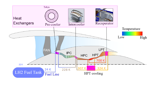
Figure 2. Heat management of LH2 fueled gas turbine. Source: ENABLEH2 poster.
The LH2 in the tank is stored at 22K. As it passes the pre-cooler ahead of the IPC/Booster (Intermediate Pressure/Booster Compressor), the H2 goes from 24K to 228K. Gradually it’s used to intercool the compressors and through a heat exchanger, cool the turbine cooling air tapped from the last stage of the high-pressure compressor. Finally, it’s heated to 700K with pressure about double that of the combustor before it enters the fuel nozzles in the combustor.
The heating of the LH2 from 22K to 700K has two positive effects:
- It cools different parts of the gas turbine core to increase its durability and efficiency
- It increases the heating value (the energy content) of hydrogen. In total, we increase the heating value by about 3kWh/kg in the chain in Figure 2.
I discussed what the practical result could be on the specific fuel consumption of a hydrogen gas turbine with Professor Grönstedt. “You can expect an improvement of 5% or more when you use the LH2’s heat sink capacity intelligently” was his answer. “There is also a lot of potential in lower emissions for NOx in the combustor process. All this needs research. We started early with heat management research and this enables us to now test the concepts from ENALBEH2 in test rigs.”
The carbon-fueled turbofan core is entering a phase of diminishing returns from higher pressure ratios and increased turbine entry temperatures. A switch to LH2 as fuel opens a smorgasbord of new possibilities around heat management and clean combustion as hydrogen burns cleaner than carbon fuels (no soot and less NOx).
Bjorn If liquid hydrogen is used as a heat sink wouldn’t this produce huge volumes of unwanted gaseous hydrogen? How would that be dealt with?
The LH2 that enters the cooling cycle in Figures 1 and 2 are hydrogen that we ultimately shall inject into the combustion chambers of the gas turbine. So we need to take it from -253°C to at least above 0°C before it enters the combustor. The more we can increase the temperature of the hydrogen gas, the more heat we get out of it when it burns (and the more power we have in the turbines). It’s a double gain.
4 ton of H2 in 2 hours. That is more than half a kilo per engine per second. You don’t have to worry about expansion for the He superconducting engine loop cooling.
Thanks.
The current liquid fuel engines could also be fitted with intercoolers and recuperators.
eg http://mdh.diva-portal.org/smash/get/diva2:1305964/FULLTEXT01 (chapter 1)
Thanks, Marc,
yes. But you don’t have the incredible heat sink you get with LH2 stored at -253°C.
Inter cooling is fairly common on aero derivative stationary gas turbines though often unwelcome on combined cycle since it throws away heat usable by the steam cycle. Clearly there is huge cooling potential in the cowling of large turbofans. Perhaps we will see cryogenic pre-cooling and air based inter-cooling one day.
The ideal engine would be duel fuel able perhaps to operate on LH2 but also able to accept a proportion of a carbon neutral synthetic jet fuel. This would alleviate the C of G issues of LH2 and bring the wings back in to use for fuel storage. The Russians built some tripropellant Kerosene/LH2/LOX rockets that performed very well though the weight of the extra pump was detrimental.
Rockets are not airplanes. Rockets like the extra trow weight of kerosene which is completely useless in subsonic planes. Having a H2/kerosene plane just makes it very complicated without any advantages. A LH2/High Pressure H2 makes more sense if LH2 creates engine start problems. But than you only need something like 5% high pressure H2 which can easily stored in the wings
I tried hard to explain the advantages of a bifuel hydrocarbon/LH turbofan. It would allow such aircraft to fly intercontinental range not just transcontinental. Yes, it’s a complication but potentially a worthwhile one. The complication could be as relatively simple as duplex bifuel nozzles and some extra plumbing and pumps. Hydrogen allows a shorter combustion chamber but we may find that a blend of simultaneously combusted fuels works fine in cruise conditions without compromising optimization for LH. It might also allow a progressive transition to airports without LH facilities.
Go full bio and it is cheaper, less complex, lighter and probably uses less fuel on long legs.
Using Reaction Engines heat exchanges opens possibilities to design jet engines to higher efficiency, higher power or lower cost materials of less heat capability, in theory making the whole hot section from Inconel 718.
Can hydrogen be used in bearing compartments like on nuclear powerplant generators its design can be made cheaper and simpler than todays where heat management is a big issue. Still hydrogen systems and structures design is not easy, just see how hard the rocket companies worked on LOX&LH2 rockets and their present preference for RP-1 and superchilled methane.
At low altitude, how can we prevent air moisture, cooled by 24K LH2, from freezing and either plugging precooler or sending ice particles to IPC blades? Even dry air freezes at 50 K. I guess that’s why the Helium loop is needed as an intermediate step. Any other fluid would freeze. But then we need to heat cold (20 K) Helium back to 70K or more. Using waste heat from cryogenic electric motors (I guess to cool down supraconductor wiring) is only feasible if we have fans driven by electric motors powered by, I guess, fuel cells. You have shown, earlier in this serie, that from a gravimetric point of view this not realistic and inefficient. Vaporizing LH2 and heating H2 gas up to 70 K is going to be tricky. We need sources of waste heat without freezing/plugging risks.
That being said, there is a lot of exergy to recover from LH2. This 5% specific fuel consumption improvement is in fact a partial recovery (20%) of the more or less 10 kWh/kg spent by Air Liquide/Linde/.. to liquefy H2. That’s a hidden 2MW electric power for your aircraft.
The anti frost system developed by reaction engines for its SABRE engine precooler has been a closely guarded secret but in 2015 reaction engines registered patents for a 3D printed methanol injection device to prevent ice formation. Note the methanol itself is a fuel and coolant as well as an antifreeze. Reaction engines needed partners to develop hence the patents.
The heat exchanger uses fine tubing – about 50km in a unit with walls thinner than a human hair.
The demonstration unit consists of about 20-30 modules, each consisting of thousands of closely arranged parallel tubes arranged in a single revolution spiral. Helium, chilled by the liquid hydrogen fuel (at below 20K) enters the spiral at the inside edge of the spiral and leaves at the outer edge.
The modules are interleaved, and the air passes through 20 sets of progressively cooler tubing from the outside inwards.
It’s a massive surface area that the air is passing over closely. Recent quotes from the company have it dropping air temperature 1000 C in 1/25th of a second.
Reaction engines will likely get rich from supercritical sCO2 heat recovery engines work as well. The sCO2 turbines are 1/10th the size of a steam turbine.
What i understood was that their secret source was a mechanical separator of crystallized ice and that they inject some stuff in the stream to seed that crystal forming.
Should be a lot of seeding and tiny crystals because the time the air spends inside the engine is so short when you are flying hypersonic.
My information on the methanol based anti-frost system comes from the Wikipedia article on the SABRE engine which notes Reaction Engines 2015 patent. The Japanese researchers have published many articles on their precooled rocket ATREX’s anti frost system and methanol is one method they propose. Reaction engines is closely guarding its IP so much is speculation. Where did you get your information from? Obviously one way to prevent frost formation is to never precool below 0C when there is a possibility of frost and simply rely on intercooling. This will be good for getting of the ground in Dubai but of limited value in some other situations. Methanol (or Ethanol) seems a good solution so long as it doesn’t react in the compressor instead of releasing its heat in the combustion chambers. There are a lot of articles but they are behind paywalls.
The HOTOL wikipedia page. Assumed because it is the same people that they would use the same method.
Remembered it also wrong. Water trap would not be normally used. Receipt is:
cool air to little above freezing
Flash-freeze it with liquid O2 to -50C (*)
let the very small and cold ice crystal just pass the engine
(*) You not only need to flash freeze the water in the air but that the air also needs to be cooled to -50C. You need a lot of liquid O2 for that. To lazy to look up the values but my suspicion is that something like almost half the O2 burned will be from the tank.Still great for a rocket, useless for a plane.
You would not cool the air until it has reached approx 50-80C, then you modulate the cooling circuits probable using a non-combustable fluid to keep the compressor air temps at close to maximum efficiency and cool the air going to the turbine blade and vane cooling. The blade cooling is the hardest as you cool the air inside the engine before the TOBI duct (tangetial air nozzles shooting cooling air into the disk/blade roots with minimum winding losses). It will be interesting to see where the FAA/EASA allows direct LH2 cooling circuits and where H/X and inert coolant is required.
The physics of frost formation is clearly involved. Hopefully we will find out here. I suspect antifrost coatings may be involved. In addition I suspect rapid cooling may prevent large ice crystals nucleating. I know in some air-conditioning heat exchangers for cold climates the exchanger is switched from counter flow to co flow below 20C to achieve this.