Leeham News and Analysis
There's more to real news than a news release.


Bjorn’s Corner: Air Transport’s route to 2050. Part 12.

By Bjorn Fehrm
March 7, 2025, ©. Leeham News: We do a Corner series about the state of developments to replace or improve hydrocarbon propulsion concepts for Air Transport. We try to understand why the development has been slow.
Last week, we wrote about Pratt & Whitney’s announcement in January: their trials with critical components of their HySIITE engine, Figure 1, showed that they could increase the efficiency of a hydrogen burn engine by 35%!
It does this by intelligently using the water released when hydrogen oxidizes with the air’s oxygen. The water separated from the exhaust is reheated into steam and entered into the engine’s combustion, reducing NOx by 99.3% and increasing the engine efficiency by 35%.

Figure 1. A HySIITE engine with its backflow core part. Source: Pratt & Whitney.
HySIITE changes the PtL SAF and Green Hydrogen balance
The 35% increase in efficiency of a HySIITE engine gives hydrogen-burn-engined airliners a clear efficiency advantage when comparing the complete energy consumption from “Well to Use” between SAF produced from renewable energy, so-called PtL SAF, and hydrogen produced from the same energy.
SAF can be produced through different methods, described in this Corner. Of these, the Power-to-Liquid SAF has no limitations on raw material supply.
To understand how hydrogen and PtL SAF are produced, see Figure 2 and the text below. It’s from an Airbus website describing the process.

Figure 2. The process to produce Green Hydrogen and PtL SAF. Source: Airbus.
PtL is a synthetically produced liquid hydrocarbon. Renewable electricity is the key energy source, and water and carbon dioxide (CO₂) are the main resources used in SAF PtL production, which consists of three main steps:
- Renewable energy powers electrolyzers to produce green hydrogen.
- Climate-neutral CO₂ – captured via, for example, Direct Air CarbonCapture – is converted into carbon feedstock.
- Carbon feedstocks are synthesized with green hydrogen—via processes such as Fischer-Tropsch—to generate liquid hydrocarbons. These are then converted to produce a synthetic equivalent to kerosene.
The process in Step 1 produces Green Hydrogen, avoiding the cost of CO2 capture in Step 2 and combining hydrogen with Carbon to produce PtL in Step 3. That’s why hydrogen organically is a lower-cost fuel than PtL at the production level.
A major advantage of PtL is that it can be transported and distributed via the existing network of fossil-fuel infrastructure, including pipelines and filling stations. It can also be filled in existing aircraft tanks and burned in existing engines.
To compensate for these advantages, hydrogen must be considerably cheaper to use than PtL SAF. This is where HySIITE changes the balance.
Figure 3 shows the energy use in a Pathway analysis presented by RTX Chief Scientist Dr. Michael Winter and Pratt &Whiney’s Technical Fellow Neil Terwilliger at the January briefing.
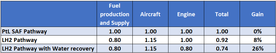
Figure 3. PtL SAF and LH2 pathway data were presented during the January briefing. Source: RTX and Pratt & Whitney.
The hydrogen burn alternative before HySIITE held an 8% energy use advantage versus a PtL SAF alternative. This advantage is so low that one must ask if the investments needed in infrastructure to supply LH2 to the planes and the changes to the aircraft are motivated.
The water recovery and reuse in HySIITE increase the advantage threefold, making a future hydrogen supply system and aircraft more attractive.
In summary, the HySIITE process produces engines with the following advantages:
- LH2 engines with the HySIITE process are 35% more efficient than today’s equivalent technology engines.
- The NOx emissions are essentially eliminated.
- The contrail formation problem of an LH2 engine is addressed.
- The net energy savings versus PtL are tripled.
Water makes Gas Turbine Engines more efficient
We have seen how capturing and re-injecting the water as steam into the HySIITE process makes the engine more efficient. The reason is that as fuel is burned in the combustor to produce a high-speed gas that drives the turbines and the fan, the mass of the gas is essential. Air at typical cruise heights has 1/4 of ground-level density. As it is compressed in the compressor, the density increases, but an air+steam mix at the same compression level will have a much higher density.
The increase in density (i.e., mass per volume) increases the power extraction in the turbines, which increases the engine’s efficiency.
Water is also produced in kerosene-burn engines but at a smaller scale. MTU, behind the WET engine process, thinks it’s still worth doing. We will discuss this engine and its process in the next Corner.
Stationary gas turbines has been using water injection for decades. Both in the inlet and mainly in the combustion chamber. It is not easy to get the water mist not to be centrifuged by the compressor to the outer wall only and so limited use at continues power. The combustion chamber housing is so hot that water can be sprayed onto its structure and not disturb the flame and you get the benefit of lower Turbine inlet temperature and increase mass flow thru the turbines. Still you can modify existing stationary gas turbines with water injection by new fuel nozzles and external system, https://www.gevernova.com/gas-power/services/gas-turbines/upgrades/water-injection-for-nox-reduction
Not water injection, heat recovery. More along the lines of Turbo compounding.
Far above my capability to assess,.
I see a lot of parts in motion but how viable it all is, phew
The engine has to be reliable, durable, and cost competitive (both to buy and maintain). Wake me up when it’s a real thing.
Yea that is my take.
The latest Gen of single aisle engines have proven to have serious issues and both P&W and CFM have done a complete go through, they used to call them PIP 1, 2 etc.
I know GE stopped that on the 787 engine, Pip 2 as I recall. A latter report said they continued mods that were really PIPs but they quit saying that. At a guess they felt it was non confidante thing or maybe a black eye to do so and just did it without saying.
GE got above the specs they original y committed to, they said so but not how they got there.
RR just came out with the Trent TEN and I think they got to their specs, but GE was ahead by 1 or 2% still.
P&W proved the GTF could be put into an engine that size vs much smaller ones used before, also reliable. Their issues were in other areas. They kind of took their eye off the whole ball. But CFM has those nit noid issues as well so not just PW.
But yea, the tech has to be reliable and durable or you wind up paying other costs.
787 has a dimpled tail (vertical?) as I recall but then the dimple filled with bugs and dirt and it was worse long term than none. So they stopped doing it that way.
787 laminar flow feature is still there in the tail.
Its being done that way on 777X too
https://www.wired.com/2013/11/manipulating-airflow-airplane-tail-777x/
@Duke:
You should note that its a 2013 article!
This is a great article about the justification of using liquid hydrogen as an aircraft fuel. From my perspective, an aircraft that uses hydrogen has to be basically designed around the cumbersome tankage (with significant weight penalties).
The use of the Steam Injected Gas Turbine cycle or STIG cycle has been around for a while. The important thing is that it is steam that is injected that has been heated by the turbine exhaust waste heat.
Water injection has been used for sometime to reduce NOx formation in the combustor, (and to help with temperature control and power output dynamic range). My understanding is that WATER INJECTION generally reduces the turbine’s overall efficiency (due to the need to evaporate the water within the engine). It is also possible to inject water ahead of the compressor or at a particular stage of the compressor to evaporatively cool and increase the density of the intake flow (a form of intercooling, not to be confused with traditional intercooling), but this can be impressively involved to achieve proper atomization, etc.
The STIG cycle is a variant of the recuperated Brayton cycle, where the gas turbine exhaust stream heats somewhat pressurized water in a heat recovery steam generator (HRSG), and this steam is injected ahead of the combustor. This helps provide sufficient mass flow to help cool components without the associated energy required to compress that mass flow in the compressor (tho one doesn’t get it totally for free).
On ground based turbines the additional equipment and added weight is not particularly a problem. Also the feed water does not have to be condensed out of the exhaust stream.
So it is an interesting concept, but one that is going to add a lot of complexity in an aircraft that has to be justified (particularly economically justified).
The main use of water injection is to lower compressor exit temperature and allow more fuel to burn to reach the same turbine inlet temperature. The other is to increase mass flow thru the turbines and allow for a higher power output. The P&W hydrogen engine has a benefit of just steam in the exhaust making the evaporation to liquid water easier still an engineering feat to make it light and durable. They usually take some years to get new stuff to work like in the sales broschyre..
I think you are missing the point that the water system PW is working on is energy recovery.
Its not being injected, its being passed through a heat exchanger and then adds a bit on exhaust.
Diesel engines use heat exchanger to cool the air after a turbo for the same reason.
The excess heat gets dumped but it makes the engine overall more efficient and you can push the turbo harder.
I was commenting on the traditional use of water injection in stationary gas turbines. P&W uses the hydrogen high energy content to make a smaller core engine, using water injection in the compressor to increase its efficiency and in the burner to increase power for a given size and at the same time reduce NOX. By burning hydrogen you get away with soot in exhaust heat exchanger/condenser. Still you have the vibrations, thermal loads to design to.
Bjorn, thanks for doing this research corner. Fascinating to think what the future holds. Appreciate your work.
I second that.
And I like to see the comments. I can disagree with some of the views but its good to see interest.
I would hate to see Bjorn quit making his corners.
Usually I can follow and get a feeling on stuff, he presents this in his usuall excellent fasion, I just don’t have any background in it so no idea if it can work and there are a number of processes from Green Fuel to Green Hydrogen mixing them and then having the system work in a jet engine.
Has my head spinning in a good way.
Noted a possible fly-in-ointment about the opinion suggested in the article and comments that hydrogen production is going to be usually GREEN (via green electricity & hydrolysis). While this MIGHT be the case in the EU, it probably will not be the case in the US.
With regard to the following issues that I will mention, it might be outdated now that Trump & company are throwing hand grenades into the the euphemistically named “Inflation Reduction Act” which is where the United States placed most of their GREEN & HYDROGEN POLICIES (gotta love those names that Congress creates).
In the US before things like large scale hydrogen production commences, the “sausage” of the policies and subsidies (placed in the tax code) have to be worked out by lobbyists, Congress, Treasury Department and then placed in the tax code by the IRS. This process has taken 2 1/2 years and is now probably being scrapped. The US hydrogen industry (of the BLUE type) is now pleading with Congress to preserve the 45V tax credit that provides substantial subsidies depending upon how CARBON CLEAN the production is. NOTE the term CLEAN and not GREEN as the Inflation Reduction Act incentivizes CLEAN and severely disincentives GREEN hydrogen production. In addition there is the 45Q tax subsidy that supports BLUE hydrogen production (carbon sequestration). Considering that the policies favored the existing energy industry and a substantial poison pill was enacted to basically shut down the green production pathway for hydrogen in the US, it is possible that they will not be thrown out. Precisely who accomplished this is a bit unclear, but the fossil industry has said that it was the solar & wind industry as the green group hate hydrogen pulling financial resources from them (personally I am more cynical).
So before we have hydrogen fueled aircraft, we first need cost competitive hydrogen production which is a complex & very expensive undertaking.
Looking forward to additional educational articles.
No question its a horrible mess right now. All areas are getting hit and put into chaos. Short term, pollution is off the table, long term it is not going away and if sanity returns, we start in again from a worse baseline.
One problem being, where is the Hydrogen used that has us with a built in infrastructure that creates the system that then aircraft morph over to using? and as a Jet fuel its not proven out even with P&W system which is all on paper or test rigs right now. About the point they were with large engine GTF when they started 20 years ago (thats a guess)
Cars?
Fuel Cells or direct.
In fact Windmills and Solar can be used to generate clean hydrogen. Frankly its the only realistic way to store their energy and particularly solar could be accommodated on its cycle.
The reality is if the world races ahead with Hyudrogen, the US will follow, we have 4 years of Trump and he may well get totally cognitively lost in under a year (or blows a gasket)
There is nothing the current admin likes, they are wreckers. What they don’t get is the wolves howl in the end while they stand amidst the ruins looking for their Micky D that has long been swept away by a Hurricane.
Heavy cars can use batteries.
Hydrogen is to small and leaks to much in normal passenger cars.
I assume its materials issue and can be dealt with.
Injection systems in diesels went into the 30k range a long time ago.
Mercedes had a Hydrogen powered car, its issue was no trunk room as the tank took up the whole back.
I’m afraid I don’t understand this at all.
You take the core exhaust and cool it to obtain water.which is a by-product of the combustion of kerosene (green or otherwise).
Last time I leaned against a recently running engine exhaust I burned my hand – that’s a lot of cooling to be done (weight, space & expense).
And that hot core exhaust was providing 20% of the thrust, maybe 10% in a more modern engine.
After the water is separated, the gas goes overboard – does it still produce thrust.
The water is heated (without cooling the gas path where does this energy come from?) and goes as steam into the combustion chamber and cools it, okay so maybe HPT cooling bleed can be eliminated which would improve efficiency, and the mass flow through the turbine goes up, which also has an effect.
Then what? The water has to go somewhere, you can’t have tonnes of it in recirculation. But if not, how does it reduce contrails?
Some comments, Yes the pressure of the exhaust after condensing and separating the water gives an acceleration in the exhaust nozzle and hence core thrust. The water circuit condenser only pulls the desired amount of water, you let the rest go in the hot exhaust. You then need to increase the water pressure and inject it back into the engine as either water or steam. At cruise altitudes the fan air stream is very cold hence you need an air regulating valve to put in just the desired amount of cooling.
Thanks Claes
I still don’t understand where the 30%+ efficiency gain comes from. The compressor delivery pressure & temperature and bypass ratio don’t seem to be affected.
And in the picture at the top of the article I can’t see the usual five or six stages of LP turbine, so what’s turning the fan? Does it have to be a geared fan with a much smaller diameter, much faster running LP turbine?
Turning the core portion of the fan airflow around 180 Deg for HPC entry – losses.
Putting a huge heat exchanger in the C duct bypass airflow – losses.
Putting the core air through the same heat exchanger – losses.
Energy to pressurize water/steam – losses.
Scavenging water to cool the HPT components instead of using bleed air – small efficiency gains.
But I have to ask, why not just design a C duct with an annular fuel cell, cooled by the fan exhaust, feed it with pressurised air and hydrogen and feed the effluent back into the engine to either cool it or recuperate it (I haven’t done the thermodynamics so I don’t know the temperature that the effluent would be, nor its pressure, but you get the idea).
Heavier (much) but it would generate electricity, unloading or even replacing the HP/Accessory Gearbox System (current gearbox accessories would need to be electrically driven) and the fuel cell would burn hydrogen more efficiently than the gas turbine.
It still wouldn’t affect contrails.
Something that I hadn’t thought of.
If the core exhaust ends up at the perimeter of the bypass gas flow after having been through a condensor, it could be injected aft into the freestream air (rather than the bypass air) and serve as a kind of jet-pump, artificially increasing the bypass ratio without altering the fan.
That would improve efficiency, I can’t say by how much.
Pre-first, I am not an expert in any of this and if anyone can set me straight, I am interested in learning. Also there is a number of complex topics that to answer even in a cursory way takes a lot of words.
First contrails:
The traditional exhaust flow due to its relatively high temperature will have the water in a vapor state which when cooled will produce a fog of very extremely small particles and hence a significant contrail (obviously using hydrogen will produce a larger contrail). With a HySIITE / WET style of turbine engine (note below other similar research programs) the condensation of some / all of the water from the core exhaust flow generates water (or at least forms significantly larger water droplets). The excess water / water droplets that are ejected from the aircraft are more like rain droplets than fog and hence the curtailed contrails. The pseudo-GHG effect of contrails seems to be dependent upon droplet size.
Other HySIITE style research programs:
Argonne National Laboratory Value Added Steam Technologies (Steam Combustor Wet combustion) or VAST Power Cycle
ENABLEH2
SWITCH engine and others
In addition a long history of using steam injection in ground based turbines (STIG) dates back to 1951 where a Swedish patent application was filed.
Your question of losses due to turning the core portion of the fan airflow around 180 Deg for HPC entry is relevant but these types of flow direction changes are typical in turboprop engines and ground based turbo compressors so the pressure losses and associated heating seem to be acceptable (I can not quantify it myself but it is probably negligible).
Your question of where can a 30%+ efficiency gain comes from requires a more complex answer than I can easily provide here so forgive the under condensed verbiage that borrowers a lot from cut and paste. Also some reference papers of varying quality are as follows:
Thermodynamic Analysis on Steam Injected Gas
Turbine cycle
Steam Injected Gas Turbine cycle
Retrofitted Gas turbine cycle using
STIG and Evaporative cooling techniques
Performance parametric analysis of retrofitted Gas turbine cycle using STIG and Evaporative cooling techniques
And numerous articles.
POSSIBLE ANSWER:
From Argonne National Laboratory’s Value Added Steam Technologies (Steam Combustor Wet combustion) program. The need for excess air / mass flow that is needed for cooling (over and above combustion) consumes a lot of power to compress that cooling air. The VAST concept is to replace that excess cooling air with water / steam that has been condensed from the exhaust stream.
The gas turbine expander operates on about 46% steam, and about 54% nitrogen (N2), and some oxygen (O2), as the hot working fluid that generates system power (these numbers vary).
Wet combustion has historically been limited by flame quenching and lower efficiency. Water injection improved power but reduced efficiency due to the energy required to vaporize the water. The hybrid cycle has overcome this issue by recycling cooling water and steam, it displaces more than 75% of the compressed air normally required to cool the gas turbines (which required maybe around 30% to 40% of the total energy produced to do this compression of excess cooling air). This added cooling mass flow from steam requires little energy input to pressurize the water while the energy to vaporize the steam is recovered from the heat that is contained in the core exhaust. So yes that energy is lost (and the pressure drop across the condenser is probably sorta lost) but that is taken out of the core exhaust thrust component (but not internal core thrust generation which is complex to quantify) which is already relatively low compared to the fan thrust. In addition the condensed water can be used for component cooling (in some designs) which reduces bleed air power loss.
The VAST Cycle combustor improves fuel mixing, controls combustion temperature heating of components with steam and water (particularly important with hydrogen’s high combustion front velocity that has a tendency to increase localized heating), and lowers peak temperatures (with associated NOx creation reduction) with improved mixing efficiency and improved residence time of the combustion process (reducing fuel slip or more compete combustion efficiency).
The amount of steam to be injected can be flexible (in the Cheng cycle) , and it may be split into three streams: a small amount goes to the fuel nozzles to control the NOx emissions another small amount is used for cooling of the turbine blades and nozzles; and the rest of the flow undergoes superheating and is injected into the combustor to mix with the compressed and heated air.
In the SWITCH engine the liquified hydrogen fuel provides a cold sink to enable increased condenser efficiency / performance. The technology challenge is developing a flight-weight and volume water recovery system.
In reference to your “C duct with an annular fuel”cell question. An another addition twist on this is that part of the hydrogen can be used in a high temperature Solid Oxide Fuel Cell that can be used as a topping cycle (name ?) that is also heated by the core exhaust thus utilizing more waste heat recovery. Tho this might not be practical in aircraft. See:
Pressurized Solid Oxide Fuel Cell/ Gas Turbine Power System
Development of a Solid-Oxide Fuel Cell/ Gas Turbine Hybrid System Model for Aerospace Applications
Turbocharged Fuel Cell Systems For Producing Electric Power
Solid Oxide Fuel Cell and Advanced Combustion Engine Combined Cycle : A Pathway to 70% Electrical Efficiency
Combined cycles of SOFC/ICE and SOFC/GT
Comparative study on the performance of the application of clean alternative fuels in SOFC/ ICE hybrid power systems on electric aircraft