Leeham News and Analysis
There's more to real news than a news release.


Bjorn’s Corner: Aircraft stability
April 13, 2018, ©. Leeham News: In the last Corner we discussed the pressure distribution on a conventional airfoil and compared it with a modern Supercritical airfoil. The Supercritical airfoil (which is used on all modern airliners) achieves a higher cruise Mach and a lower transonic drag by accelerating the air over the wing to a lower supersonic speed than conventional airfoils.
What conventional and supercritical airfoils share is a pressure distribution making them unstable. We need to stabilize them on an aircraft.
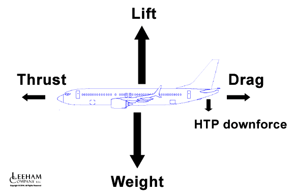
Figure 1. The primary forces on an airliner. Source: Leeham Co.
Airliner pitch stability
We saw the airfoil pressure distributions on our conventional and supercritical airfoil had most of the lifting force at the front. This front heavy lifting force increases when the angle of attack of the airfoil is increased.
The wing on its own is unstable. It risks tipping over when subject to gusts (coming from below, they will increase the angle of attack) or when a pilot commands to high angle of attack against the air.
This is what happened to Northrop’s original flying wings before artificial stabilization could stop the pilot from raising the nose too far in the B2 bomber.
For an airliner, one will not trust artificial stabilization to save the aircraft from tipping over (for a Military bomber like the B2 and forthcoming B21 it’s OK). The aircraft must be naturally stable, meaning if all control systems froze, the airliner shall not tip over backwards like a B2 could do when subject to a strong gust.
To configure the aircraft with a canard stabilizing surface, like the Rutan VariEze (or Beech Starship) requires the canard surface to be highly loaded to guarantee it stalls before the main wing stalls (the aircraft then lowers the nose, increases speed and regains stable flight).
The high loading of a limited span canard will create unacceptable levels of induced drag. This is why canards are mainly limited to military aircraft which can be designed as semi-stable or unstable, taking away the high loading of the canard wing.
Horizontal tail configurations
When the stabilizing surface is placed behind the wing as a horizontal tail, it works better. The horizontal tail can be designed with both positive, neutral or negative lift in normal flight. The designs with positive or neutral lift are trickier to get right and therefore uncommon. We will focus the common horizontal tailplane type, the ones with negative lift in normal flight.
Figure 1 shows an aircraft with a normal airliner arrangement of the wing and tailplanes. We can see the centre of weight is configured so lift has its centre a little behind the centre of weight. This is deliberate; otherwise, the aircraft would not be controllable in pitch with a simple horizontal tail set at a fixed incidence. The nose down tipping moment produced by the difference in centres for lift and weight is called the aircraft’s (static) stability margin.
To counter the tendency for the aircraft to dip the nose, the horizontal tail is working as a small wing flying upside down; it produces a small down-force. By it, it bends the aircraft nose up by the lever caused by distance to the aircraft centre of gravity.
When the wing experiences a gust, which increases the angle of attack of the wing and lessens the (inverted) angle of attack of the tailplane, the downward force of the horizontal tailplane will reduce. The centre of gravity will now tip the aircraft forward, as the tail is no longer as strong in keeping the tail down.
The tipping of the aircraft forward will increase its speed. The wing’s increased lifting force then tips the aircraft nose up, as does the increased downforce from the tail. The aircraft gradually finds an equilibrium, called the trimmed speed.
In the next Corner, we will discuss aircraft stability further, as the trimmed speed will not be fully stable.
Why is it that “for an airliner, one will not trust artificial stabilization”? Obviously a combat aircraft with just one or a few seats is likely to have an ejection route should things go wrong, but do these systems actually go wrong appreciably more often than other components of a civil airliner could?
I think it’s a principle. The artificial stability assumes a rather complex system, from sensors over computers to hydraulic servos all work correctly. If a lightning strike or an un-probable failure kills something in this chain and its backups then hundreds of passengers perish. This is unacceptable.
An FBW A320 can fly and land with only the horizontal tailplane trim and the rudder, which both have mechanical backup control, ie it can fly without the whole FBW system.
Ok, thank you Bjorn.
Bjorn – love the series!
Could you comment on the MD-11 and its certification with “relaxed longitudinal stability”. If I remember correctly, MD was able to certify this plane with a much smaller horizontal tailplane and with a further aft CG because they had longitudinal control computer augmentation. All this was in the effort to achieve the expected fuel efficiency. This relaxed longitudinal stability was complicit in the famous PIO accidents the type has experienced (FedEx PIO crash at Tokyo Narita probably the most widely known).
Both the 777 and MD11 have augmented stability. The 777 is positive but closer to neutral than possible without computer assistance. The MD11 is neutral so augmentation is absolutely required, at least for certification if not flight. Here is a Boeing article about how stability varies with altitude.
http://www.boeing.com/commercial/aeromagazine/aero_02/textonly/fo01txt.html
Interesting point about MD11 relaxed stability and fuel savings.
I have noticed that FR, when aircraft are just slightly less than full, tend to cordon off the first two or three rows to push pax towards the rear of the plane. This has stuck in my mind because I found it odd that they do not cordon off equal rows at the back, so it appears to be a deliberate unequal distribution over CoG.
Presumably this “operational relaxation of pitch stability” results in a small fuel economy. It appears FR really are quite shameless, in their pursuit of cost savings.
Brilliant corner. Never knew that there was negative lift on the tail plane. Always assumed it was positive.
Trying to remember back to my college textbooks, but I’m pretty sure they had positive lift on the tail plane.
Lift on the horizontal stabilizer doesn’t have to be negative for a longitudinally stable airplane, although it usually turns out to be the case, as Bjorn mentions. In textbooks the direction of the lift vector on the horizontal stabilizer is usually drawn as upwards, because that is its positive direction, although its value is usually negative. There are two conditions for a statically stable airplane, and one of them is that the angle of attack (from the zero-lift line) is greater for the forward lifting surface than for the aft lifting surface (and ‘lifting surface’ refers to a canard, wing, or horizontal stabilizer). The second condition concerns the location of the center of gravity. The webpage https://www.adac.aero/raymer-annotations contains notes to accompany Dan Raymer’s textbook ‘Aircraft Design: A Conceptual Approach’. Read the notes for sections 4.5.2 Tail Arrangements and 16.3.2 Pitch Static Stability. The notes aren’t exactly self-explanatory, because they contain numerous references to Raymer’s textbook, but might be of some help.
Something related to aircraft stability:
Russia may stop titanium deliveries to Boeing
https://www.rt.com/business/424003-russia-will-stop-exporting-titanium/
Good one.
Wait till the RD180 rocket engines stop arriving for military satellite launches.
Falcon can only do lower weights and some orbits.
I don’t think this is correct. What about the Falcon Heavy? 141,000 lbs (64 MTs) to LEO.
Too risky as its not reliable enough and with all those engines should anything go wrong ?
Satellites are expensive things to roll the dice with, so may take another 8-10 years to take over completely.
Thats the point Im making, US isnt good at everything in spite of what the fanboys think
Falcon Heavy is able to boost more than double the mass to LEO than either the Atlas V Heavy or the Delta IV Heavy.
for about 20% of the cost.
also, the current Falcon 9 Block 5 has more mass to LEO than any single core version of the Atlas V or Delta IV regardless of how many strapon SRBs you bolt to them
How many bookings does it have ?
Thanks Bjorn, nowhere else on the internet is such educational info available for us folks that just wonder about things that fly.
Just spent a weekend in Hammondsport, NY, at the Glenn Curtiss Museum. Your info is just a bit of a fast forward of what they learned from basic engineering & seat of the pants…
Doesn’t the issue of wings having an unstable center of lift go all the way back before Kittyhawk. My understanding has always been that excessive fore and aft movement of the center of lift (all the way forward going up, all the way back to the trailing edge coming down) was a major factor in Otto Lilienthal’s death. I was also under the impression Wilbur Wright spent more time with his wind tunnel developing the first iteration of the teardrop shaped airfoil than correcting Lilienthal’s lift/drag tables. Perhaps he patented the wrong invention and should have let wing warping alone.