Leeham News and Analysis
There's more to real news than a news release.

 Leeham News and Analysis
- GE testing of giant GE9X engine aims for maturity at entry into service June 30, 2025
- Bjorn’s Corner: Air Transport’s route to 2050. Part 28. June 27, 2025
- Parent agency, FAA often at odds as politics outweighs safety June 26, 2025
- Electric Flight and the Ugly Duckling June 25, 2025
- Engine makers tout “Plan A” but have “Plan B” backups in R&D June 23, 2025
Bjorn’s Corner: New engine development. Part 14. The compressor problems.

By Bjorn Fehrm
July 5, 2024, ©. Leeham News: We do an article series about engine development. The aim is to understand why engine development now has longer timelines than airframe development and carries larger risks of product maturity problems.
To understand why engine development has become a challenging task, we need to understand engine fundamentals and the technologies used for these fundamentals.
We covered the basics of how a compressor works last week. Now, we look at the challenges in compressor design (there are plenty).
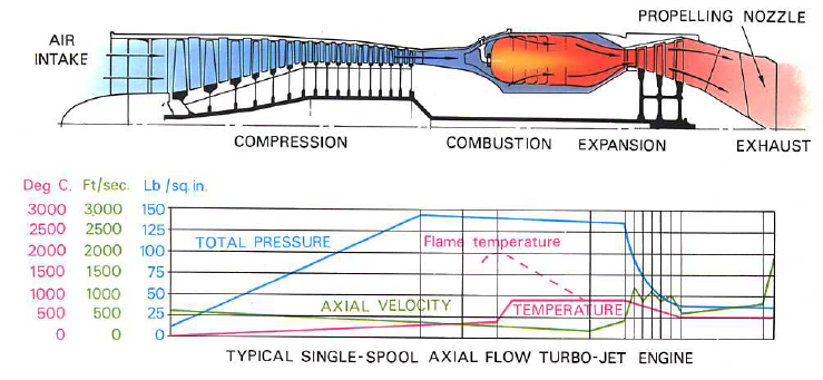
Figure 1. The gas turbine cycle and its parts. Source: Rolls-Royce: The Jet Engine.
Compressor challanges
The most common compressor is the axial compressor as it’s easy to daisy-chain to achieve high-pressure ratios, and it results in a low-diameter gas turbine core.
You need compressors with high-pressure ratios to achieve efficient combustion and a large expansion of combustion gases in the combustor. Pressure ratios of modern engines at cruise are around 40:1 for single-aisle engines and 50:1 for the latest widebody engines. At takeoff and climb the engine spins faster to generate more thrust, and we see pressure ratios of 45-50 and 60 for the two engine types.
As compressors grow in stage numbers to achieve higher pressure ratios, stability problems creep up at different thrust settings. As we raise the air pressure, the volume decreases, and the density increases. To maintain a reasonable axial velocity of air that takes less volume, the annulus area of the compressor decreases with each stage (Figure 2).

Figure 2. The axial compressor. Source: Rolls-Royce, the Jet engine.
When designing a compressor with its many blade and stator rows, you optimize the aerodynamics for the dominant thrust condition of the engine, the cruise. This means that the maximum thrust at takeoff operates the engine aerodynamically a bit off the peak efficiency, as does the climb thrust setting (but to a lesser degree, it’s closer to cruise).
The operation of an engine core at the cruise and higher thrust settings is usually not aerodynamically challenging (thermally, it is, but we come to that). The flow through the engine works fine, though the transfer efficiency of turbine power to compressor pressure might be some percentage units of the peak.
The challenge for the compressor is when we need to reduce thrust for descent and landing. Now we need less thrust and thus less massflow through the core as we won’t need so much hot gas to drive the turbines. When the massflow of air slows down, the trouble starts in the compressor.
The air hitting the rotor blades now hit the leading edge of the blades at a higher angle of attack, AoA, similar to a wing flying at low speed. At some point, the blade boundary layer separates, and we have a growing blade stall. This can develop into a rotating stage stall, stopping the airflow through the engine.
The expansion of the air in the combustor no longer has a high-pressure compressor stopping the gas from going down the compressor path. We have the spectacular engine stalls (also called burps) that you can see on YouTube videos, where compressor flames are visible spitting from the engine.
The engine loses all thrust for a short while, and then, most of the time, the compressor recovers as the backpressure from the combustor diminishes. Thrust is generated, and the stall starts again if the engine thrust setting is unchanged.
Compressors use variable-incidence stator vanes for the initial stages (Figure 2), which are adjusted to decrease the blade AoA at low thrust settings. To avoid a stall, you could also bleed air from the later stages, thus increasing the air mass flow through the compressor. The bleed valves, leading compressor air into the bypass channel, are visible as flat-top mushroom-type chimnies protruding from the engine’s core in Figure 3.

Figure 3. Rolls-Royce Trent 1000 with two compressor bleed valve outlets. Source: Rolls-Royce.
Split compressors
A way to reduce the problems described above is to avoid having a compressor with many stages. Instead, compression is divided into a low-pressure compressor and a high-pressure compressor, each driven by its turbines through concentric axes.
We now have two shorter compressors that work together to achieve the overall pressure ratio. Typically, in a two-shaft engine, the fan and low-pressure compressor are on one shaft, with a total pressure ratio of around three. The high-pressure compressor then has a pressure ratio of 15 to 21, resulting in the overall pressure ratios we discussed above when these ratios are multiplied.
The special case is the three-shaft engines Rolls-Royce and Ivchenko design, where the fan has its own turbines and shaft, followed by the low- and high-pressure compressors, Figure 3. Rolls-Royce likes to call the low-pressure compressor the intermediate compressor; it’s semantics.
Compressor efficiency
Key to engines with low fuel consumption and, thus, low emissions are high-pressure ratio compressors with high efficiency in converting turbine power to pressure. There has been a big jump in efficiency in the last 20 years. We look at how this is achieved in the next Corner.
Thanks for again the information!
When I see compressor stalls happening on planes, it is mostly with take-off. I never have seen it really on descent or landing. Am I looking to the wrong videos?
As you say, during the descent the thrust setting is low and you have a high angle of attack, thus a stall could be lurking. While during take-off your thrust setting is high, which can lower the influence of the high angle-of-attack.
The engine designers have managed to get the low-power stall tendency well under control with the three means I described (split compressor, variable vanes, and late-stage compressor bleed).
The stalls you see are where an engine stalls under high power due to wear or any other issue. The compressor and engine, in total, are under high stress during takeoff. Anything non-normal can cause a problem in the compressor that can develop into a stall.
A good example for Take-Off stall is bird ingestion.
You have a foreing object disturbing the airflow locally that will result in local compressor stage stall. If the disturbance is large enough it can spread to full compressor stall.
Depends a bit how you measure efficiency, normally a turbofan has its lowest TSFC at max power at sea level as you burn the fuel at the highest air pressure. The HPC blade tip gaps during different conditions can be hard to control and design, lots of turbofan engines have had this problem that can cause compressor surges P&W, besides variable vane hysteresis that can cause troubles and broken vane links GE. You also have start up stalls (sub idle rotating stalls) RR.
“The challenge for the compressor is when we need to reduce thrust for descent and landing. Now we need less thrust and thus less massflow through the core as we won’t need so much hot gas to drive the turbines…..To avoid a stall, you could also bleed air from the later stages, thus increasing the air mass flow through the compressor. The bleed valves, leading compressor air into the bypass channel, are visible as flat-top mushroom-type chimneys protruding from the engine’s core in Figure 3.”
This intrigues me as where my father used to live was in the general area of part of the racetrack circuit for an international airport. The Widebodys coming over would make distinct engine noise for maybe a few seconds that I thought was related to the step changes in altitude.
But It might be the airflow dumping into the bypass section as they reduce speed ( no brakes!) which also allows the step down for changing altitudes They were maybe 2-3000 ft ?
Stanley Hooker, the famed Rolls Royce engineer who saved the RB-211, pointed out that one of the major advantages of the three spool design was that one could have ample margins against compressor stall without having to have row after row of variable stator vanes. I think the RB-211 made do with just one row, all the other stators were fixed. Competing 2-shaft engines were (are?) festooned with variable stator stages.
The advantage was that there was far less to go wrong in the engine overall; they traded the minor complexity of three shafts for the significant simplicity of omitting (almost entirely) variable stators.
When one looks at a compressor, it’s easy to see why compressor performance is difficult to achieve; it’s essentially empty fresh air with a few slithers of metal poking out into it. That it can hold back huge pressures (present at the combustor inlet) is remarkable. This indicates that all those blades are having to do a significant amount of batting the air molecules in the right direction. It’s easy to see that imbalances in what all those blades are doing (e.g. a stuck variable stator) could easily cause merry hell.
Yes. The GE9X indeed has issues just before its first flight ( 2018 ) with the lever arms for the high pressure compressor variable stators
Theres been further issues around 2022 but unlike RR problems , GE gets it away from general media as ‘unspecified issue’ and behind pay walls Bloomberg who has a close association with GE only reports good news