Leeham News and Analysis
There's more to real news than a news release.

 Leeham News and Analysis
- GE testing of giant GE9X engine aims for maturity at entry into service June 30, 2025
- Bjorn’s Corner: Air Transport’s route to 2050. Part 28. June 27, 2025
- Parent agency, FAA often at odds as politics outweighs safety June 26, 2025
- Electric Flight and the Ugly Duckling June 25, 2025
- Engine makers tout “Plan A” but have “Plan B” backups in R&D June 23, 2025
Fundamentals of airliner performance, Part 5; Approach and landing
By Bjorn Fehrm
Dec. 2, 2015: The time has now come to cover descent and landing in our ![]() articles around airliner performance. As many aspects of descent are similar to climb we will repeat a bit what we learned in Part 4:
articles around airliner performance. As many aspects of descent are similar to climb we will repeat a bit what we learned in Part 4:
- For high speed operation the pilots fly on Mach as this gives him maximum information around possible effects on the aircraft when he is close to the high speed limit, the maximum Mach number. Beyond this the aircraft gets into supersonic effects like high speed buffeting or unsteady flight.
- For operations under the cross over altitude for Mach 0.78 to 300 kts IAS the pilot flies on Indicated Air Speed (IAS) which gives him maximum information how the aircraft reacts should he go close to the aircraft’s lower speed limits.
Lets now start to go through the steps that our 737 MAX 8 performs after leaving its cruise altitude.
Descent from cruise altitude
The descent rate like the climb rate depends on the amount of excess thrust over the aircraft’s drag, only in descent we don’t talk about positive excess but negative. This means the pilot has to reduce thrust under the drag of the aircraft to make a descent at constant Mach or lower down at a certain IAS. The normal engine setting for descent from cruise is flight idle which gives a very low thrust from the engines.
When a descent from cruise can be started is very much dictated by requirements from Air Traffic Control (ATC) and this clearance was often given so close to the destination airport that speed brakes (normally the part way deployment of the wing spoilers) had to be used for keeping the Mach and later IAS to the desired level. Use of speed brakes is a waste of hard earned potential energy and therefore the industry is today trying to maximize economy and total fuel consumption by a descent that can be started so early that a continuous optimal speed descent can be flown all the way to the final approach for landing. This maximizes the potential energy that the aircraft gained when climbing to cruise altitude. The target for modern ATC is therefore to have flexible enough descent and approach procedures to let that happen.
Speed wise the descent is very much the inverse of the climb. Initial descent is normally at cruise Mach, 0.78 in our case. This is kept until the altitude where M 0.78 is meeting the gradually increasing IAS of 300 kts (see part 4 for an explanation of this cross over between Mach and IAS). The 300 kts IAS is then kept until entry into the Terminal Maneuvering Area (TMA) where we are asked to keep 250 kts until final approach is commenced. The 250 kts is once again to keep aircraft from overtaking each other during approach and landing. One of the requirements on ATC is that they arrange for proper separation of aircraft during the approach and landing procedure. The separation varies depending on local air traffic rules and quality of radar coverage but is normally 3 nm close to the airport but can be up to 10 nm if the radar coverage has low resolution.
Should the weather conditions allow, the ATC can ask the pilot if he would accept making the final approach under Visual Flying Rules (VFR). If the pilot OK this, the separation responsibility passes to the pilot and separation can normally be reduced or a more efficient final landing procedure can be used. The normal procedure is to route the aircraft to a point 10nm straight out from the landing runway, where the aircraft have an altitude of 2000ft over the runway. From this point a standard ILS glidepath is flown, either under Instrument Flight Rules (IFR) or VFR rules. An ILS glidepath has an angle of 3° (5.2%) and is normally followed also for straight in visual approaches as one can then check the aircraft’s vertical position by glancing on the IFR glideslope indicator.
Final approach and landing
The most important thing when landing is to get the speed low enough so that aircraft can be brought to a stop on the runway available (which might be wet or even slippery of snow) but also in order to give the pilot more time to react and correct any miss alignments there might be during his landing procedure. Normal speeds on the last 10 miles for modern airliners are 120-150 kts, our 737 MAX 8 would be close to the predecessors 142 kts.
To get our 737 MAX 8 to fly at the desired speed of 142 kts at maximum landing weight of 69 tonnes or 153,000 lb we need to create lift from the wing of the same magnitude. If we divide the lift of 153,000lb with the wing area we get the lift per unit wing area at 535kg/m2 or 116 lb/ft2. An even more used measurement is the lift coefficient, Cl, which also takes the air density and aircraft speed into account. Using this universal measurement we need a Cl of 1.7 to fly the approach at 142 kts at our maximum landing weight. Figure 1 shows how we achieve this lift at the low speed, it shows the high lift devices which are used during landing.
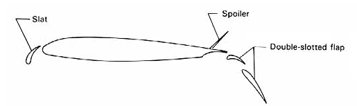
Figure 1. Typical landing configuration for a modern airliner with slats and flaps deployed. In this case also the spoiler is deployed to slow down the aricraft. Sourc: Leeham Co.
On the leading edge there is a guiding vane called a slat. It serves to increase the canting angle the wing can use relative to the approaching air, the so called angle of attack or Alfa angle. Figure 2 has plotted the lift coefficient against the Alfa angle for a wing without and with slat on the first curve from the bottom. This figure is a generic diagram and not specially drawn for our 737 MAX but serves to show what we want to explain.
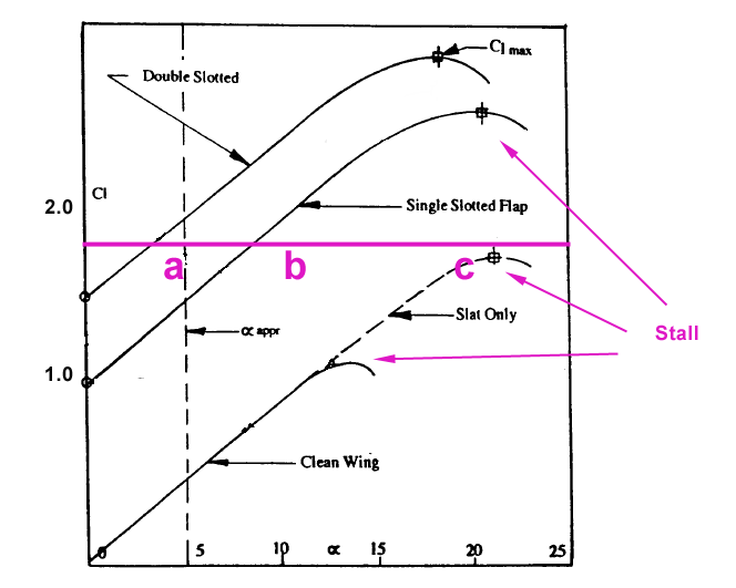
Figure 2. Landing configuration diagram showing lift force coefficient, Cl versus angle of attack for the wing. Source: NASA
With a clean wing the aircraft has zero lift when the wing has no angle of attack (Alfa is zero), it then increases linearly until 13° angle where the wing goes into stall and the lift force reduces with increased nose up attitude of the aircraft. The reason for the wing stalling is that the air stream can not follow the leading edge, it curves to abruptly. If a guide vane in form of a slat is deployed the wing works all the way up to 20° angle of attack.
On the other end of the wing flaps are deployed (Figure 1). They serve two purposes:
- The increase the wings lift capability by curving our air downwash stronger downwards, thereby giving us the needed lift at 142 kts.
- To lower the aircraft’s attitude. As can be seen in the diagram we could have reached Cl 1.7 (the violet line) by almost slats only (c) or by a simpler single slotted flap (b) which would be lighter and easier to maintain than our double slotted flap (a). But this lift would have been reached at a very high Alfa angle and thereby nose up attitude. The pilot would have had difficulties seeing the runway and the tail would risk hitting the runway when touching down.
Assuming that 5° angle of attack is the max which would be acceptable given these reasons we can see that a single slotted flap system would not work, our needed 1.7 Cl would be reached at 8° Alfa (b). Although the diagram does not fully describe the situation for our 737 MAX 8 it shows that we need a double slotted flap to reach Cl 1.7 below 5° Alfa angle. In practice our MAX 8 has a double slotted flap on the inner part and a single slotted on the other part of the wing. With this combination it reaches the necessary lift at an acceptable Alfa angle.
Drag during landing
It is important that the final glideslope of 3° angle can be flown with enough engine thrust so that there is margin to slow the down the aircraft or descend faster should this be needed. This can only be done by reducing thrust further or deploying the spoilers partly to act as speed brakes (Figure 1). The speed brakes increase the drag, drag is therefore not a negative during landing, there are aircraft types (Fokker F28 and Avro RJ / BA146) which are landed with deployed air brakes for this reason.
Our landing configuration is quite draggy so we do not need the air brakes, the excess thrust over flight idle is there to allow the pilot to fly the final approach and landing with enough thrust margin to give him a finer adjustment capability than the air brakes could give him. Higher drag is a positive for fine adjustment on the glideslope but also a positive from another aspect, the go around procedure. Should one not see the landing lights at the minimum height (often around 200 ft for ILS approach) an abort of the landing needs to be done (an abort is also the prescribed action for many other types of disturbances during landing). When performing such an abort, or Go Around as it is also called, the engines needs to responds fast with max continuous thrust. This response time is helped if they are not spooled down to a very low thrust during approach.
A landing configuration is therefore quite draggy, this is achieved with flaps extended to the landing configurations (full or close to full angle) and below 10nm with the landing gear extended. At go around full continuous thrust is selected and gear up is commanded, thereby we remove drag and get more thrust quickly, we get a positive acceleration of the aircraft and can gain speed and height. Soon after gaining speed and height flaps and slats are reduced to takeoff settings and then retracted fully like described in our climb clinic in part 4.
Touchdown
Just before passing the end of the runway the pilot reduces the speed to the so called reference speed Vref, for the 737 MAX about 5 kts lower than our final approach speed. Vref is defined as a speed which is 30% higher than the stall speed in the landing configuration and works as the guiding speed for all other speeds during the landing. Our final approach speed is therefore often given as Vref + XX kts (5 in our case) in aircraft manuals.
Once passed the end of the runway, or threshold as it is also called, the pilots starts the flare where he gradually raises the nose while reducing thrust to touch down with minimum speed. When both main landing gears are loaded the spoilers deploy in full to take away any remaining lift (they are also called lift-dumpers), this in order for the aircraft to stay safely down with good weight on its wheels. After having reduced the speed to taxing speed we turn off the runway and taxi to our gate.
Summary
We have described the descent from cruise and our approach and landing of our airliner. The descent is very much an inverse of the climb with the same speeds being used for the same reasons.
For the landing we use an extensive high lift configuration to get the landing speed down, this is quite draggy but we don’t mind. We need a certain amount of drag to give the pilot margin to regulate his glidepath by changing his thrust but also to reduce spool-up time for the engines should he need to execute a go-around.
We have now covered all parts of a normal flight, in the next part we will start looking at some of these phases a bit more in detail.
Hi Bjorn. Thanks again for interesting article.
I am interested in spool-up time.
How log does it take (e.g. on cfm 56) to spool up to the full thrust from idle, flight idle or landing thrust configuration.
Generally, how many seconds does it take from decision to go around until the plane stops descending and starts to climb.
Is there huge differences in spool-up time of different engines for the same aircraft (e.g. A320ceo)
When in a descent, I can imagine that the kinetic energy (downwards) prevents the plane to climb straight after reaching full engine power. How much time does it take to counter normal descent?
Also a quick question, which major European airports facilitate a glide decent proactivly?
Cheers
Bob,
My experience is that “it depends.” What is the aircraft’s configuration? What altitude and speed? How rapid a climb is needed? In my experience, an aircraft is capable of stopping a descent nearly instantly and at least starting a climb using excess airspeed (typically we are as much as 40 knots (or more) above a stalling speed unless in the flare for landing where the margin is less). If we are told to “go around” while in the flare, we will probably bump the mains on the ground (and the spoiler and brake software knows not to deploy if go-around thrust is commanded).
Boeing puts fantastic wings on their airplanes. On most of their designs the aircraft is limited by geometry (the tail hitting the ground during takeoff or landing). A full-on, maximum performance climb from an approach or landing configuration is pretty dramatic for the passengers and unless terrain avoidance was an immediate concern would be atypical for commercial operations. In normal operations a level off, or climb out at 1,000 to 2,000 feet per minute is all that is required to satisfy a missed approach. The aircraft is capable of going to 6,000 feet + FPM in just a couple of seconds (depending on configuration, weight, temperature and altitude).
Kamil,
You raise an interesting point which merges with a comment I was thinking of making. On the 737NG the engine design is limited by having a single stage high pressure turbine, resulting in greater than desired lag between commanded thrust and the engine spooling up. This design is mitigated through software which both maintains a higher idle rpm and commands an increase to 40% N1 if the auto throttles think they will need power. (ie as the aircraft captures an altitude in the descent the engines spool up in ANTICIPATION of the need for increased thrust for level flight).
Mr. Fehrm’s theoretical discussion, while good, does not include every variable and the CFM 56’s quirks manage to upset the perfect VNAV idle descent more often than not. At top of descent the 737 tends to over-speed, causing the autopilot to go high on it’s path as it tries to correct the speed. As it loses path it reverts to speed mode, causing the pilots to intervene using flight spoilers. Use of Engine Anti Ice protection exacerbates this problem as the engine has to maintain higher power (and higher idle thrust). The VNAV software has a forecasts page to enter anti ice use, but outside of me, I’ve only seen a couple others use that feature.
Experienced pilots mitigate these effects by reducing the descent speed at top of descent. Then some will purposely command less than ATC assigned speed knowing that the aircraft will overshoot by about 10 knots. I trade 10 knots in the descent for a smoother arrival with less autothrottle / spoiler corrections.
The writer picked an interesting airplane for the discussion. The small inlet necessitated by the short landing gear and high idle trust make the 737 the “slickest” airplane I’ve ever flown. The 737NG – particularly the -800 teaches energy management better than any other design I’ve flown certified under Part 25.
Is there any minimum “spool up” required for certification ??
My question is poorly worded sorry
Is there any MAXIMUM “spool up TIME” required for certification ??
Hi All,
regulations require (in a simplified view!) go-around performance to be calculated with the thrust the engine reaches 8 seconds after selecting go-around thrust, when spooling up from that thrust level used on final approach. Therefore the engines are usually designed in a way that, generally, maximum thrust will be reached approximately 8 seconds after setting go-around thrust (if approach thrust was selected before). There are more details to it, of course, but the above should be a reasonable first assumption.
All the best,
Matt
If I am not wrong, at ISA/Ground level engines must accelerate from flight idle to 95% in max. 5 seconds (FAR Section 33.73(d)).
This acceleration time however increases subtantially with the increase in altitude. I have experienced engine accelerating in more than 1 minute from Flight Idle to Max.Continuous. This results in flight crews sometimes aborting a successful engine re-start at high altitude, driven by the impression that the engine does not accelerate.
Hi Bjorn,
This is the part I liked best, because I learnt a bit more than I knew. Thanks.
A modest suggestion. In professional presentations, it is important to avoid even trivial errors re spelling etc. since they needlessly distract the reader. This is why archival journals have technical editors, who also make sure that the article is free from such errors. And as a scientist, my nightmare is to have such an error in print with my name on it. So …
A common mistake that many people make is in using “then” and “than” incorrectly. The same goes for “effect” and “affect.” This article contains the former error. It is a good idea to avoid it. Hope you do not mind my pointing it out. I hasten to add that this error in no way diminishes the utility of the article.
The wing loading noted (535 kg/m2) is doubtless correct but the U.S. conversion noted (360 lb/ft2) is wrong and would imply a very small wing. The correct number is +/- 110lb/ft2. Will we ever just go metric?
Thanks Kant and Dan, it should be corrected now me thinks.
the whole series has been well done, thank you.
What I find disturbing,, is that ATC (or ACT, grin) is now obligated to reduce fuel use as well as maintain aircraft separation and movements.
Safety is supposed to be the paramount missions and I think it is compromised by throwing that non safety related aspect in that is not ATC responsibility or should be in their purview.
I know of one pilot who also thinks the continuous descents keeps the crew scrambling all the time and not time to assess the situation. Not a good thing.