Leeham News and Analysis
There's more to real news than a news release.


Bjorn’s Corner: Embraer’s Fly-by-wire approach

By Bjorn Fehrm
08 April 2016, ©. Leeham Co: Two weeks ago we discussed the advantages of a Fly-By-Wire (FBW) system which uses feedback based flight laws. We discussed the fact that aircraft OEMs can get the desired FBW handling characteristics with smaller horizontal tail surfaces. I put forward the Embraer E-Jets as an example where the change of FBW principle allowed a 26% reduction in the horizontal tail size for the E2 generation.
At the time there were some debate on how this was achieved and what the root cause of the improvement was. Embraer followed the discussion and told me when I contacted them that my information was correct. In the interest of our readers, Embraer agreed, however, to have their FBW team to give a more complete picture of the advantages of a feedback based FBW.
Here is the team’s response.
Gains with feedback based FBW in the pitch channel
Figure 1 shows the Embraer E-Jet E2 Center of Gravity (CG) envelope with an open loop FBW (an open loop FBW behaves like an electrified classical control system and is used on Embraer’s E1 generation) and with their new feedback based FBW for the E2 generation.

Figure 1. Position of CG range for open loop and feedback based FBW. Source: Embraer.
The more aft-loaded CG range is achieved by placing the aircraft’s wing in a more forward position. The more forward position of the wing reduces the pitch up moment (the tail downward force times the distance to the aircraft’s Center of Gravity, CG) that the horizontal tailplane must produce to keep the aircraft stable, Figure 2.
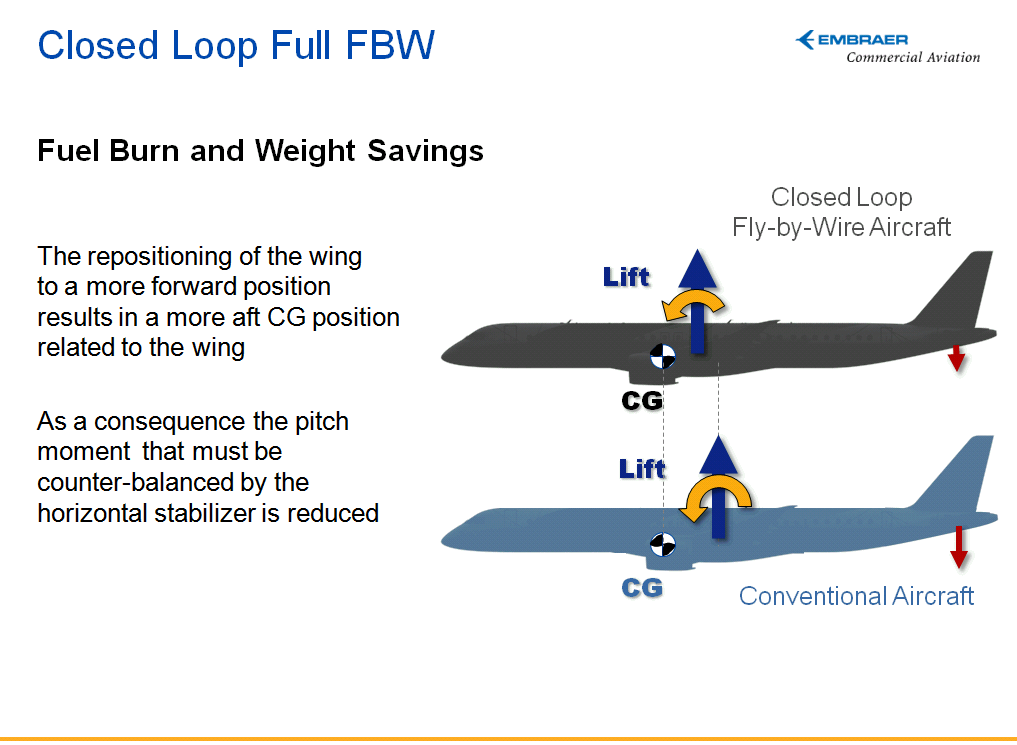
Figure 2. Pitch moments for adequate control stability with different FBW. Source: Embraer.
The result of a lower moment is that the counterbalancing capability of the tail can be reduced. This then allows the horizontal tail size to be reduced, Figure 3.
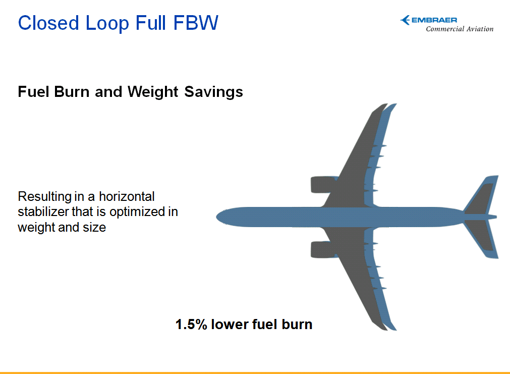
Figure 3. Horizontal tail size for a full feedback based FBW and resulting drag reduction. Source: Embraer
As the pitching down moment gets reduced and horizontal tail size gets smaller, two positive effects results:
- The reduction in size of the horizontal tail leads to a reduction in friction-related drag as the tail’s wetted area is reduced. To this, one can add a small reduction in pressure drag.
- The lower counterbalancing pitching moment means the downward generated force is reduced for the horizontal tail. This reduces the tail’s induced drag and it also reduces the induced drag of the wing as this must carry the aircraft’s weight + the tail down-force.
The total result of the change from an open loop FBW on E-Jet E1 to a feedback based FBW for the E2 is that the fuel consumption of the E2 is reduced by 1.5%, everything else being equal.
Thank you Bjorn, very enlightening.
Would it be rude to ask you about why no canards on airliners, and as an ex Standard Austria sailplane pilot have never totally understood why butterfly tails have never caught on. Much lighter and cheaper, and I am sure yaw control in the engine out condition is not an insurmountable problem?
– Canards (mounted in a conventional location) disrupt the flow ahead of the wing leading edge. This has an adverse impact on wing L/D, which isn’t wholly compensated for by the eradication of trim drag.
– Not sure on butterfly tail. Yaw control shouldn’t be a problem when you’ve got a FBW system that can interlink the “rudders” to the ailerons to remove the roll element. Perhaps the stability & control bunch aren’t ready to make that leap.
– Many aircraft already use the ailerons for load distribution manipulation. But, by coupling MFS spoilers and the ailerons, there is the potential to reduce vertical tail volume too* – if any aircraft use this (even without the reduced v-tail) – it has escaped my attention.
*Although perhaps during approach in a high cross-wind, demands on the flight control system and the aerodynamic platform are arduous enough without additional requirements being heaped on.
the B2 and other flying wing designs have abandoned the vertical stab entirely by using clamshell style split control elements near the wing tips to control yaw.
Boeing proved that their BWB (X-48B) that good crosswind landing control could be achieved with a combination of split control elements and articulated winglets (getting double duty out of the winglets as combined lift improvement and flight control surfaces)
The later X-48C model reinstated vertical tail surfaces not for improved control margin, but as a way to demonstrate ground level noise reduction (by effectively shielding the engine inlet and exhaust with the body and vert stab.
Drone sized aircraft are not really comparable. Still ended up with vertical control features on both versions. And putting a rudder on your angled vertical service indicates more than just ‘noise control’
they had eliminated the other vertical surfaces and the flight control system was not engineered for operation without some rudder equivalent effectuator.
they went to great lengths to ensure scale representative aero behavior. I would tend to think NASA and Boeing know what they are talking about in this respect.
I love that Embraer is reaching out to the enthusiast community. That’s a sure-fire way of earning my respect!
Thank you Björn,
While obvious, never really though of this positive aspect of FBW in the dynamics of aicraft stability and control.
Basically the FBW solution allows the aircraft to be operated with narrower stability margins. This resulting in a smaller drag and smaller aircraft structural weight. Great.
The next step could be an active “CG Correction System” that would correct the position of the CG (eg. by fuel distribution) so that in stable flight conditions the stabilizers are most of the time on “zero load” condition.
Maybe someone is already using such a system?
Fuel tanks in the h-stab are used on most long range aircraft already to try to minimise trim drag.
As I remember the A340 was the first commercial aircraft to use such a tank.
The 747-400 has a tank in the horizontal tail. About 3,300 gallons. As I recall the 747-400 first flight was in 1988, A340 in 1991.
But was it able to shift the fuel to adjust the centre of gravity while in flight ? It was used for the 747-8 to do that , but for the 747-400 around 30 years ago ?
It seems that the tail tank was ‘used first’ on older planes.
For the A330/340 this seems to be a good description
“During the climb at FL255 with certain other conditions fuel is pumped aft to achieve an aft CG target set by the FCMC (computor) (even if the tank was empty on take off) This is about 2.5pc fwd of the aft CG limit. As fuel is used the CG moves aft and when it reaches a target of 2pc fwd of Aft Cg, then fuel is pumped fwd into the centre or wing tanks.
There is usually only one aft transfer in each flight, but there can be many fwd transfers.”
http://www.airliners.net/aviation-forums/tech_ops/read.main/345165/
I was not talking about the pure existence of a horizontal tail tank rather the use of the tank to move the fuel automatically during flight by the FBW system.
The 747-8i has FBW but can still not use this tank due to a shifted center of gravity. According to my knowledge the tank is there with all the pumps but the FBW is not capable to use properly.
For the 747-8 it was certification issue concerning flutter in some cases that prevented the aft tank being used.
These tank issues were resolved as part of an improvement package announced at the end of 2013.
The 747-8 doesnt have FBW in the usual meaning of the system. It only has outboard ailerons using digital signalling via ‘wires’.
Its not clear that its more than a simple ’empty first’ type of rebalancing rather than the more advanced systems available.
Concorde was the leader in the moving fuel around in flight for aerodynamic purposes, which is why Airbus was able to have the more advanced systems in conjunction with digital FBW for its widebodys.
It seems the A350 uses its variable camber wing to achieve the same results, but others may know if the fuel movement to and from the tail tanks is still done.
Wow – great article. Certainly great innovation by Embraer.
Perhaps extending this concept, the vertical stabiliser could also be reduced in size if some auto-correcting or compensating rudder controls can be introduced. Fighter jets use this concept to make unstable designs fly control-ably. If small verticals could react with faster rudder inputs, with smaller inputs than that of a pilot- overall the smaller drag will also give fuel savings.
The 777, for example, has automatic rudder input for engine out control. The FAA Vmcg certfication specifies certain pilot reaction time for rudder input and a maximum deviation from rwy centerline during the recovery. Automatic rudder input would either reduce Vmcg, or allow for a smaller vertical tail for a specified Vmcg. Take your pick.
I thought there was more to it, but did not want to write a chapter on all criteria that apply to CG limits on commercial transports, which BTW are quite different from MilSpec requirements.
By moving the wing forward, horizontal tail volume, Vh, increases, Vh=(Lh*Sh)/(Sw*Cw), because tail moment arm, Lh, increases. It would be interesting to know how much the Vh increased due to wing relocation. Moving the wing forward shifts the CG range aft, since the CG range is defined in terms of % MAC (Cw in the Vh equation); and assuming that the wing itself is the same on the 190 and 190E-2. For same control power as before, the increased Vh would allow corresponding reduction of the horizontal tail area, Sh, assuming everything else is the same.
Nothing has been said what happened to the main landing gear location in terms of % MAC, which is one of the hard limits for aft CG for airplanes with nose gear. No FBW system will change that. From nose wheel steering point of view the minimum allowable distance between the aft CG limit and the main gear location is 2-3% MAC on airplanes that do not have pitch-up at power application, such as airplanes with aft body mounted engines. On airplanes with under-wing mounted engines, where the thrust centerline is below airplane CG, power application produces a nose up pitching moment which requires more margin between the aft CG limit and the main landing gear than the 2-3% MAC, or nose wheel steering will be lost. On airplanes with thrust centerline below airplane CG, the minimum distance between the aft CG limit and the main landing gear is dictated by the TOW, engine thrust and the thrust moment arm. No FBW system will compensate for this.
In case the original aft CG limit was dictated also by main landing gear location (which is the case on well designed airplanes) mowing the wing forward would require relocation of the main landing gear or restrict the aft CG limit so that acceptable nose gear steering is maintained. Relocating the main landing gear would be a major redesign. Was that done?
The TOW-CG charts appear to be ‘for illustration only’, showing identical CG envelopes, with one shifted aft and both clearly indicating identical CG restrictions due to nose wheel steering criteria. An airplane where the in-flight aft limit changed due to stability augmentation systems, or higher thrust engines, would show a different CG/TOW envelope.
FBW, open loop, closed loop, etc, is just words. A stability augmentation system that allows a commercial airplane to be certified for CGs aft of the natural aerodynamic limits dictated by the most critical location of the neutral point and the maneuver point, would require 4 completely independent systems, including hydraulics, like on the MD-11, which went too far in horizontal tail size reduction and ended up with very marginal elevator control power at the forward CG limit. Did the ERJ 170/-75/90/95 already have the required system redundancy to allow artificial extension of the aft CG limit with the “closed loop”, or did Embraer redesign those systems as required for a full time pitch stability augmentation system?
I could go on, but so what. There obviously is more to the story. On the 190 E-2, the 26% reduction in horizontal tail size was primarily due to wing relocation, suggesting that the wing was in the ‘wrong place’ to start with on the -190, and that “closed loop” is an excuse for redesign. The ERJ-170 to -195 had four different fuselage lengths and two different wings, which is an accomplishment by itself. It is possible and likely that production cost savings from structural commonality resulted in slight suboptmization which is not atypical at all when it comes to different size airplanes of the same basic model. Now when the E-2 family is reduced to 3 models, each airplane will have optimized/different size wings, new engines for better gas mileage, increased MTOW, more fuel volume for better range, and other refinements such as a further stretch of the 195 E-2. The -195 has not sold that well, and the E2 modifications should help that one quite a bit.
Andy,
the wings on the E2 generation are totally new in concept and design. The wing is placed further forward on the 190 which is the only one with similar fuselage length to the E1 version. What I can see we are talking about 0.8m or thereabouts. The tail arm from CG to HTP aero center is around 17.5m i.e. we are talking about a change of +4.5%. The tail size is -26% so the total moment capability has a clear reduction. The volume is affected by the E2 wing being larger, both in area and MAC. I have changed in the article to not involve tail volume.
The landing gear goes from simple struts to cantilever and the reason could be to increase weight on nose gear, I don’t have the location differences. The E-Jet first generation system was a electrical analog wire replacement of steel wires with stability augmentation with limited authority brought in from a digital computer in an analog mixer unit for each channel. Redundancy is from several channels working on the movables. The E2 is a 100% redesign, all digital with proper flight law logic, software done by the Embraer team. If I remember right the E2 system is a quadruple system for the required redundancy.
Bjorn, many thanks for further clarifications. It is pretty clear that the reduction in tail area was due to many factors, and not only a closed loop system. A big swinger is a new wing. For example, if the flap system was changed for less complexity, lower maintenance costs, less noise and less pitching moment at max landing flap, a smaller horizontal tail could be used with proper balancing of the wing/body/tail design, while keeping in mind all certification requirements at the CG limits, many of which having nothing to do with stability augmentation systems.
E2 wing area is 20% bigger than E1. It is difficult, if not impossible, to reduce the controls requirements only by achieving less CM0 from flaps. CM0 would have to be reduced by more than 20%.
The best way to reduce the tail control requirements is also reducing aircraft stability. It may be proved mathematically that the tail incidence required to trim is proportional to aircraft static margin.
Bjorn
MLG on E2 might have changed from telescopic to articulated to pull back the wheel so to avoid tail bumpers since it’s quite long fuselage due to the 4 abreast arrangement.
E2 FBW system is a complete redesign compared to E1. E1 has no augmentation on the pitch axis.
AFT cg limit is severely restricted by landing gear positioning. E2 has trading link landing gear, which may be positioned further along the aircraft wing chord.
E2 cg envelope is not only aft compared to E1. It is larger.
E1 tail is not the same along the entire family.
E2 landing gear positioning is not the same as E1.
You need more information, man.
Bjorn:
Well done and thank you and Embraer for following this and providing the answer.
Can you comment on this if its relaxed stability aka MD-11 per Andy?
He seems pretty invested in this and [Edited as a violation of Reader Comment rules].
@Transworld:
I have about 20 years hands-on experience with military and commercial airplane flight control system design and development, requirements, certification and flight testing.
Please do me a favor and leave me out of your comments. Regarding the MD-11 you can find all info on internet.
The same guy that denies an aircraft that has the VSI winding down at 10,000 fpm and no forward speed and denies an aircraft is stalled?
I will leave it to Scott to decide if I am out of line.
Transworld: You are confused again. I never said that the A330 was not stalled. It was in stall all the way down.
Andy:
When I read things like the following
“An airplane without “stall protection” would have pitched nose down at stall and recovered.”
the A330 was without stall protection at that point.
I have to wonder who is confused and does not understand aerodynamics .
Transworld:
Scott told you to stop it, and I’m asking you to do that also.
If I have to step in a third time, TransWorld will be suspended from commenting for a week.
I remind everyone to re-read Reader Comment rules. This sort of direct engagement, innuendo and in some case direct insults (such as the Prozac comment) are forbidden.
Hamilton
Roger, guilty as charged.
The E190e2 looks like it has a tall landing gear to fit the engines, which should be a plus for rotation angle. But, how much of a penalty is it for landing gear weight and servicing the aircraft? Is this the most efficient solution, or will the truss braced wing bring aircraft closer to pavement? Will the tail look like the Caribou to get the rotation and moment arm.
There is probably a very good reason recent braced wings have been only on (some) smaller aircraft. [ Thats if the recent news wasnt an April 1 thing]
Even for larger bridges the truss approach seems to have mostly been replaced by efficient designs. When its getting too heavy for a bridge , it isnt time to bring it back for planes. Designed in flexibility is now seen as a good thing.
Sounds good. This FBW and smaller horizontal stab. is a further refinement on the template for the most efficient solution for an airliner. The twin engine twin main gear, from the E195e2 to the A321, to the 777-9.
The 777 will continue with 6 wheel main landing unit. Small airliners use twin wheels, larger ones with quads
I was thinking the 777 and A350 have gone with two legs versus the DC-10-30 and A340 with three legs for high weights. A further refinement or an arbitrary choice?
Truced braced wing is a real thing.
http://aviationweek.com/awin/nasa-boeing-test-low-drag-truss-braced-wing-concept
that would be one of the ideas for an out of the park home run for Boeing to do and negate the A320 completely!
the primary issue with Truss Braced Wings (TBW) is the penalties associated with aerodynamic compression drag at the truss/wing join area exceed the weight benefits on same length wings and if you want to use a longer wing you need to either go up a gate class or 2 (expensive and inefficient use of airport facilities, higher landing fees) or you need a folding mechanism which adds weight, complexity and maintenance.
recent aero research has been making inroads on the compression drag issue and if Boeing can prove the weight/complexity/cost vs efficiency trade with the 777x fold, then TBWs become a more attractive option.(likewise Airbus’s down fold patent holds promise, but has limited utility in terms of length of wing beyond the fold.)
Bilbo:
As we have seen, the 777X design makes for a simple wing fold mechanism. It has to be neither maint costly or weight costly.
It does require a lot of work to keep all the working surfaces inside the joint.
The TBW in the Av Week article does have the folding wings.
The wing folding you describe has been the case for naval aviation for over 80 years. Keeping it inside the the wing itself, is the easy bit.
http://blogs.crikey.com.au/planetalking/2014/02/09/boeing-patent-locks-folding-wingtip-logic-updown/
“As we have seen, the 777X design makes for a simple wing fold mechanism. It has to be neither maint costly or weight costly.”
777X hasn’t even flown yet and reliable data from airline use aren’t available.
( 787 had sky high attributes associated to no end. mostly up in smoke .. and the mirrors are broken.)
Andy and TransWorld: Stop it.
Hamilton
Amen!
Scott:
My apologies. I did not see your responses. Regardless I should not have gone there.
What about the tail tip sensitivity of the E2?
As the mail gear goes foreward there will be more weight aft of the main gear. How much did it travel foreward?
What is the MAC equivalent of the main gear station of the E1 versus E2? Is there any diffirent platform handling because of this?