Leeham News and Analysis
There's more to real news than a news release.


Bjorn’s Corner: Fly by steel or electrical wire, Part 4

By Bjorn Fehrm
August 16, 2019, ©. Leeham News: In our series about classical flight controls (“fly by steel wire”) and Fly-By-Wire (FBW or “fly by electrical wire”) we this week discuss the Flight Control System’s authority to execute maneuvers by its different parts and why the authority of these parts is a fundamental parameter when designing the system.
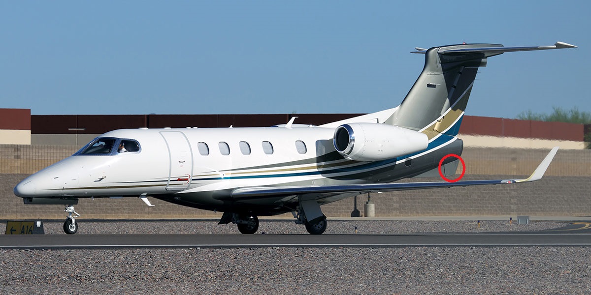
Figure 1. Embraer Phenom 300’s Yaw damper rudder. Source: Embraer.
The authority decides the system design
To further our discussion about different flight control systems we need to introduce a key parameter: Control Authority.
The Control Authority of a flight control function sets how useful and powerful it is but also how dangerous it is if something goes wrong.
To understand the importance of control authority lets take the example of an airliner’s yaw control function. Normal operation is the Pilot moves the pedals with his feet to control how the rudder on the vertical stabilizer is moving and by it how the aircraft yaws. He uses this to yaw the aircraft into a turn while rolling the aircraft into the turn with the ailerons, to get a coordinated turn (a coordinated turn means the aircraft is not sliding through the turn but flying it with zero lateral G). He also uses it to control the yaw of the aircraft when landing in a sidewind.
Airliners also need an automatic function called a Yaw Damper which moves the rudder to counter a tendency of aircraft to snake in the air with a movement called a Dutch Roll. I have described the background to the Dutch Roll and its movements in previous Corners, so I only summarize; The compromise an aircraft designer strikes between the Spiral stability of the aircraft and if it Dutch Rolls, tends to end with accepting an aircraft with a bit of Dutch Roll and to dampen this out with a Yaw Damper.
A Yaw damper is a servo which is working on the rudder and applying anti-Yaw commands to stop the Dutch Roll’s wagging of the tail. This happens without the pilot noticing it in his pedals. It’s a control function with limited authority as it only deflects the rudder with small amounts to stop the Dutch Roll tendency of the aircraft. Hence, the Yaw Damper function doesn’t need a lot of redundancy or oversight functions. If the Yaw damper misbehaves, the Pilot notices a non-dangerous Yaw anomaly and switches the damper off.
A good example of how the authority is limited is the Yaw Damper implementation of the popular Embraer Phenom 300 business jet, Figure 1. Here the Yaw damper has it’s own rudder, the little one below the tail at the end of the ventral fin. Authority of the damper is limited in a very natural and visible way.
Let’s compare this with the Pitch channel in a feedback loop Fly-By-Wire system like the A320. As described last week the pilot asks for a certain G or Pitch rate. He leaves it to the FBW system to achieve this.
This concept gives the FBW full control of the pitch control surfaces and with full authority. If a fault in the system commands a full elevator or trim deflection, the aircraft can be overstressed and break up. The authority of the systems is so large, a fault with dire consequences cannot be allowed to happen during the lifetime of the aircraft. In fact in the lifetime of the fleet of aircraft of this type and for all their flight years.
It’s clear the level of authority of systems is key when designing flight control systems. It decides the system solution, the redundancy required, its availability and its check concepts. It also decides the architecture of its infrastructure systems like electrics and hydraulics.
We will discuss such different solutions and their probability of failures in the next Corner about Flight Controls.
Should mention that the Phenom 300 copied the design of the SJ30 for the ventral yaw damper… https://www.syberjet.com/sj30
If I have it right, the 747-8I used a control sequence to deal with flutter with the tail tanks filled.
What happens if that type of a system fails?
I keep reading about they tweak this and that with the controls surfaces in that regard and wondering on those as well for a possible failure?
Its covered in the story:
“It’s a control function with limited authority as it only deflects the rudder with small amounts to stop the Dutch Roll tendency of the aircraft. Hence, the Yaw Damper function doesn’t need a lot of redundancy or oversight functions.”
However compare the pitch control surfaces in a Control Loop FBW:
‘The authority of the systems is so large, a fault with dire consequences cannot be allowed to happen during the lifetime of the aircraft. In fact in the lifetime of the fleet of aircraft of this type and for all their flight years.”
No faults in the lifetime of entire fleet of the type.
If it were the Phaenoms ventral rudder fin or maybe a split rudder limited authority would be a fact. In the 1990s there were a series of hard over rudder issues on the B737-200 and 737 Classic (USAir 427, Eastwind 517, United Airlines 585) that involved the duel servo valve that operated the single rudder with a single hydraulic actuator. All souls aboard 427, 585 lost their lives but the crew of 517 managed to recover the aircraft though it was 585 that finally revealed the flaw. This was a classic case of having a single point of failure which was deemed improbable and that a catastrophe was considered recoverable by the crew but in reality wasn’t below certain speeds. It seems principles from those crashes weren’t learned. The usual script of blaming pilots occurred. Clearly a split rudder is a great way of limiting the effects of a fault in either yaw damper or rudder command path. In a FBW system there is a standby actuator and it is possible to bypass the primary actuator and engage the secondary. In my view FBW vastly safer. I have not heard a single incidence of FBW failing except that case of all hydraulic system bleed out after a missile strike on a DHL A300 over Baghdad.
The Perpignan A320 air crash was a chain of failures ( as they usually are) but FBW algorithm involving the 3rd and last accurate AOA indicator did decide to ‘vote’ for the two wrong AOA indicators ( hopefully I got that right)
https://www.flightglobal.com/news/articles/sensor-icing-caught-out-a320-crew-in-perpignan-crash-347457/
page 92
“When the real angle of attack increased, the blockage of AOA sensors 1 and 2 at similar values caused the rejection of the ADR 3 anemometric values, even though these were valid. This rejection was performed by vote without any check that the parameters were consistent with each other”
The flaw seemed to be 2 similar but wrong values overrode the single right one !
This wasnt the principal cause, that was allowing the 2 AOA sensors to get waterlogged during a ‘ fuselage wash’ 3 days before the flight.
An observation was the original test plan was based on those done by manufacturer ‘test pilots’ and these were run of the mill airline pilots without that training. Then they couldnt do the original tests so cobbled up a new one at low altitude, and didnt become aware of the change of flight control laws ( from normal law to direct law and later to abnormal attitudes law) from the sensor malfunction.
I may have missed something as I only have a basic understanding.
This is often referred to as XL Airways Germany Flight 888T, it was a delivery acceptance flight being conducted by the XL crew on Behalf of Air New Zealand with Air NZ staff on board. I don’t regard it as a failure of the FBW system because all of the flight control surface remained completely controllable. You could regard it as a failure of the flight envelop protection system. 3 of the 4 ‘alpha’ sensors that measure angle of attack had been filled with high pressure water from an improperly conducted paint removal procedure the day before. Three sensors then froze simultaneously in the same angle and with the forth free unit at the same angle no alarm was raised till it changed. When the crew did conduct a stall test with inadequate altitude for a recovery the 3 congruent faulty sensors voted out the functioning 3rd sensor and the stall prevention not activate through the stall alarm did activate. This could have happened to a non fly by wire aircraft because stall warnings, stick shakers and stick pushers would also have not activated.
I can see two ways of preventing this 1/ Introduce better heating of the sensors to prevent icing 2/ use a different type of sensor for 2 of the 4, I would suggest the pressure null type used on fighter aircraft. This issued two offset pressure ports the are driven into zero pressure difference by a motor. Because the probe is motor driven it is possible to rotate the drive to check its operation. It’s also possible to retract it. 3/ do a plausibility check using Inertial navigation and GPS data to estimate the likely angle of attack.
“Fehler Offenbarung.”
A rather difficult item in bringing up save systems
is making sure that all things work.
they are designed for exposing but continuing to work a single fault in a sane way.
IF you power up with multiple faults that causes the system never to enter faultless state working order
and without indication.
( This is an issue with switching off…on safe systems to begin with. defects are not necessarily dependent on being powered up. thus you can accumulate two defects in a row while powered down.
Powering up enters a state with double error where only single error exposure has been shown. ups.)
There were 3 not 4 AOA sensors.
It certainly is a ‘fault’, there being no suggestion of complete system failure.
That fault should be in the ‘never ever’ category as mentioned by Bjorn
As the BEA said -“This rejection was performed by vote without any check that the parameters were consistent with each other”
Duke: I am talking about things like the 747 could not put fuel in the stabilizer tanks as they had unacceptable flutter.
Clearly you don’t fly if its on the ground and failed but what happens if you are in the air say 10 minutes out and it fails?
With the software and tweaks working they could use the tanks.
Without it?
Wasnt the answer to not use those tanks and put the planes into service until a fix was resolved ?
https://www.flightglobal.com/news/articles/boeing-locks-out-747-8-tail-fuel-tanks-on-flutter-concerns-367148/
“…it was discovered that, under a certain regulatory-required structural failure scenario, the airplane can experience flutter events when the fuel tanks in the horizontal stabiliser are filled over 15% of their capacity”
There was a previous flutter issue during flight testing involving the wing tips and the essential fix before certification involved the FBW outboard ailerons.
https://www.seattletimes.com/business/in-person-fitzgeralds-fix-for-boeing-747-8-earns-aviation-honors/
This of course raises the issue of the ‘safety’ side of FBW controlled ailerons ( in a fly by steel cable plane) which only have small deflections and dont seem to have a big effect on the planes path but are working to prevent flutter which could be very dangerous.
If the aircraft experiences flutter (i.e. aeroelastic flutter of say the wing or tail plane) or control surface flutter the immediate solution may to simply slow the aircraft down a little or whatever is advised in the aircrafts flight manual. Long term the flutter can cause fatigue so must be engineered out. In this case we have vibration sensors or accelerometers measuring the vibration and are aware of it even if the damping system has failed. These flutter dampening systems aren’t dealing with the kind of severe flutter that could break an aircraft apart in a dive.