Leeham News and Analysis
There's more to real news than a news release.


Bjorn’s Corner: The challenges of Hydrogen. Part 6. Tank placement.
August 28, 2020, ©. Leeham News: In our series on Hydrogen as an energy store for airliners we look at the challenge of placing the hydrogen tanks efficiently.
Different from carbon fuels, liquid hydrogen needs specially shaped and bulky tanks. It can’t be stored in the wingbox as today’s Jet-A1.
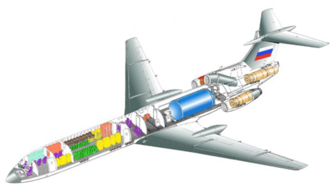
Figure 1. The Tu-155 Hydrogen research aircraft with its aft fuselage tank. Source: Tupolev.
Where to put the liquid hydrogen tanks on an airliner?
After discussing the need for a cryogenic (a very low temperature, -253°C), low pressure, tank-type in last week’s Corner we now look at the placement in the aircraft.
Our present hydrocarbon fuel, Jet-A1, is stored in the void space formed by the wing’s central structural element, the wingbox, Figure 2.
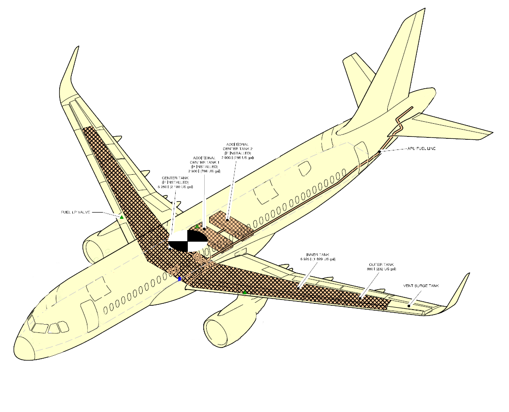
Figure 2. The placement for the fuel tanks on an A320. Source: Airbus.
I’ve added the approximate placement of the Center of Gravity (CG) of an A320 (approximate as it varies between ~15% and ~40% of the mean aerodynamic chord) as a circle with black and white sectors.
Observe how the fuel is positioned around the CG, with the center tank slightly ahead and the outer tanks slightly behind the CG. Extra center tanks are also placed as close as possible to the CG.
It’s all to minimize the change in CG during flight as the tanks go from filled to empty. With fuel management among these tanks, where the center tank is emptied first, the CG variations during a flight are kept small.
A typical two-hour mission for these aircraft (an 800nm trip for A320/737-8), consumes four tonnes of fuel whereas a four-hour mission takes 7.5 tonnes ( a 1,500nm air distance trip).
If we assume that a hydrogen version of such an aircraft consumes 35% weight wise of what a hydrocarbon fueled aircraft consumes, we have a consumption of 1.4 tonnes LH2 for the short trip and 2.6 tonnes for the long trip.
We don’t want this variation to take place too long from the center of gravity of the aircraft.
The tanks are heavy, typically two to three times the LH2 weight, but this can be outbalanced statically by moving the wing forward-aft on the aircraft.
For short-haul aircraft, where the fuel weight variation is small in relation to total aircraft weight, an aft tank can be accepted, Figure 3.

Figure 3. For short-haul aircraft an aft tank placement is acceptable. Source: Airbus.
As we progress to larger aircraft where the variation of LH2 weight is a larger portion of the total weight of the aircraft, we start to place the tanks so LH2 can be pumped around to keep CG variations within limits, Figure 4.

Figure 4. LH2 tank placements for a short/medium range airliner. Source: Airbus.
The ideal placement of tanks is fore and aft in the aircraft fuselage. Figure 5 describes tank placement in a large long-range aircraft.
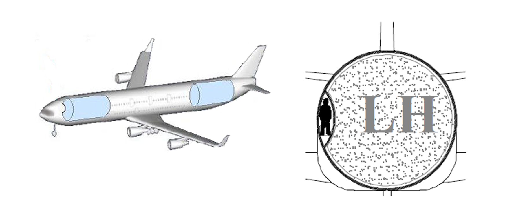
Figure 5. LH2 tank placement when the LH2 weight variations are large. Source: Airbus.
The problem to solve is access to the cockpit during flight. With the last year’s closed cockpit doors, one can question if a catwalk to the cockpit beside the forward tank is needed. It’s a phycological question if passengers feel safe with pilots in a compartment that is hermetically separated from the passenger cabin or not.
As we can see from these sketches from the Airbus Cryoplane project, the tanks are not perfectly cylindrical. As the tanks are low-pressure designs it’s the heat leakage that must be optimized. Slight variations from a cylindrical shape are then possible.
The solution for tank placement of the first hydrogen test aircraft can be an aft placed tank as in the Tu-155, Figure 1.
If the maximum range is kept within limits, an aft placed cylindrical tank is an acceptable solution. Once the appetite for more range increases, more balanced designs are necessary.
LH2 has a density of .07g/cm³
JPn has a density around .8g/cm³
11:1 !
energy per mass is 3 times that of Kerosin.
raw storage volume required is thus 3.8 higher than jet fuel.
Add the additional volume needed to allow cryogenic storage.
expect something like a zeppelin with wings than a traditional airplane layout 🙂
Actually I could imagine a central fuel tank with
passenger accommodation in elongated gondolas on the wing or the reverse. traditional fuselage with
cigar shaped tanks under the wings. ( engine integrated into the rear cone? some concepts around to work the boundary layer.)
Flying wing
Or two parallel tube fuselages, maybe with a small centre tube for the LH2?
Remember back to the first double aisle plane the 747, it was a big task to get the airlines to go for a centre seat bank , it was unconventional and previous concepts were for upper and lower single aisles as that was all they knew.
“Or two parallel tube fuselages, maybe with a small centre tube for the LH2?”
A330: 140m³ volume available for fuel,
LH2 equiv 532m³ ( 140 * 3.8 )
With a 222″ / 5.6m diameter fuselage tank ( as on A330 )
that amounts to a 30m long tank. Add cryo packaging/insulation.
As I wrote: a fat cigar or two for LH2 fuel and a smaller tube for passenger accommodation.
Hmm, something like the Junkers Ju-38
pax space in the wings and the fuselage carries the fuel?
Uwe,
we don’t need 140,000L for an A330,
100,000L should be fine for 6000nm.
You are aware of how (first order) estimation works for engineering?
Uwe,
it wasn’t meant as critic,
we need to make it work, right.
We need to reduce range too, so 3500nm for an A330-900 should allow for maybe 240 pax for a transatlantic flight.
If someone has the block fuels for 3500nm we could calculate closer. I’m sure LH2 on an A330 could work.
An A330-900 would have 200 pax with around 6000nm,
but it would look better with 3000nm.
“”expect something like a zeppelin with wings””
Yes, say goodbye to narrowbody.
A normal A321 has 23490 L fuel, that would be an LH2 tank of 89500 L.
Cabin width is 3.70 m, so I calculate with 3 m inner tank diameter which would make the LH2 fuselage tank 12.63 m long.
Cabin length without cockpit is 34.44 m, so 21.81 m would be left for doors and pax, so 120 pax only.
A330 fuselage should be better.
Or baggage in the wings and a tank in the hold
T(h)anks Uwe,
yes, now is the time to be creative! This is the major challenge of LH2 airliners, the engine piece (which we will come to) is trivial in comparison.
Did not many Aircrafts have access to the cockpit thru the fwd landing gear bay? In theory the copilot could do the pushback, park the truck and take a sporty short walk to the Aircraft and climb up into the cockpit thru the FLG bay while the captian starts the engines?
No, its not pressurized and it is full of forward lading gear to boot.
Thanks Bjorn for this new part of LH2 corner!
Although figure 3 to 4 architectures seems promising from a CG point of view, they would induce heavy stress on the fuselage. Weight impact may be sensitive.
As Uwe pointed out, a centre wing box mounted tanks architecture would be more interesting. Having two separate cabins may not be an issue on long range A/C.
Figures 4 and 5 architecture are interesting because they assume that tanks shall be within the fuselage pressurized area. It would drastically reduce design constraints regarding environmental requirements.
Regarding having a cockpit separated from the cabin, I think it would less appeal pilots than the passenger since it would mean no service from cabin crew. In addition, it would require additiinal dedicated lavatory, rest room and cooking area for long flights.
The fore/aft tank arrangement would seem to be the most efficient, if we stick with the traditional wing & tube design. Two tanks minimum are needed for redundancy, and two large tanks minimize the heat transfer and resultant losses. Also easier to build. Several smaller tanks add cost, weight and loss.
There is a potential issue with tank leakage, as CG and balance would be adversely affected. So perhaps the fuselage extensions and tank placements would be partially over the wing, or immediately before and after, with aisle on either side. If there is space between, perhaps it could be used for restrooms or other utility. Or forego the aisles as Bjorn suggested. There could be strong containment & protection bulkheads between passengers and tanks, front and rear.
Pumping LH2 across long distances will entail higher losses as well. So having tanks close to the engines would be another advantage.
I suspect all solutions will be non-ideal to some extent, so have to consider all options and choose the least overall risk & penalty. Moving away from traditional tube & wing provides more options, but higher development and certification costs
Why needs the cockpit to be in front?
The 717 has fuselage mounted engines, so most of the weight is in the back, which moves the wings back too.
The front fuselage before the wings is long and could be made even longer for LH2 tanks in the front.
Often the fuselage is more high than wide. Better might be more wide than high, so more seats could be in one row which would make the pax cabin shorter, so the most pax weight could be more centered.
Have EAS/FAA come up with any special certification requirements for H2 Aircrafts yet? Just red Aw Week and Universal Hydrogen turboprop conversion proposal.
Is there any particular reason why the LH2 tanks should not be an integral part of the fuselage to save weight? Similar to the kerosene tanks in the wings?
There certainly need to be extra insulation, but CFRP barrels should be ideally suited for the purpose.
Regarding the placement of the tank. Maybe it could still be in the center of the fuselage with a round (or oval) tunnel connecting the front and rear passenger area.
“”Regarding the placement of the tank. Maybe it could still be in the center of the fuselage””
In figure 5 the pax cabin is in the middle because pax are heavier and the pax weight stays the same during flight.
The passengers are heavier in total but their weight is distributed. For short range, each tank would weigh 2 to 3 tons, in the span of 3 m or so, with support and safety equipment included. That’s if the storage efficiency goals of the white paper can be achieved.
It’s good to have your fuel weight near the CG, because it does change during flight. LH2 would be more difficult to transfer for balance, especially from one end of the aircraft to the other.
The tanks need to be double-wall thermos-like construction. CFRP tanks have been built for
LH2. The main issues are brittleness and matching of the thermal expansion coefficients for the materials used in the composites. So the composition is optimized differently. Perhaps with additional research the tanks could become more integrated with the fuselage.
The tunnel idea could be done, but would allow more heat transfer, thus driving greater losses. In general you want to minimize the ratio of tank surface area to volume, for cryogenic fluids. That’s partly why spheres and cylinders are preferred.
All solutions involve trade-offs, so it’s a matter of considering the various options and deciding which are most effective and/or least costly. There is no one right way to about it.
I calculated the empty tank and the tank might even be havier than pax, so figure 5 is not a good example.
Gundolf is right,
the fuselage tanks are heavier than pax and this is really good, so there can be business class in front, tank in the middle and economy in the back.
LH2 is possible with a big cross section fuselage, but forget about long range.
How long will it take till we see it? Should be the next generation.
I agree, having integral Al-Li friction stirr welded tanks integral with a Al-Li fuselage makes sense. Bjorns/Airbus sidewalk can be replaced with a center tube with a slide letting pilots/C.A. notify the pilot of the transfer and have the aircraft make a slight pitch manuvre to make a swift and quick ride thru the tube similar to the astronaut travels between modules.
When I was at university, I had the opportunity to read a book “Hydrogen Aircraft Technology” by G.D. Brewer. A very interesting book covering both
subsonic and hypersonic passenger aircraft. Unfortunately, this book is not very accessible. It covered tank design and insulation and many other aspects.
I understand it’s a classic. It’s available on Amazon in Kindle format, just bought it.
@Björn Fehrm
This
Study of LH2 fueled subsonic passenger transport aircraft
Authors:
Brewer, G. D. (Lockheed-California Co. Burbank, CA, United States)
Morris, R. E. (Lockheed-California Co. Burbank, CA, United States)
https://ntrs.nasa.gov/citations/19760012056
(NB: Available as a pdf file)
–
Conclusions and Recommendations are on page 122 (i.e. page 103 in the document).
–
NB: On page 85 (or page 69 in the document), there’s a description of a two class A380- sized 400 seat double-decker: 😉
–
So, the question then is how a state-of-the-art LH2-powered twin VLA design based on Brewer’s and Morris’ concept, but using a fully composite A380 fuselage, all new high aspect ratio wings and two UltraFan engines, would perform (i.e. Range, TSFC, OEW, MTOW etc.) in comparison to Brewer’s and Morris’ LH2-powered VLA concept from 1976.
Another option is a blended wing-body design, along the lines of the CHEETA concept NASA is sponsoring at the University of Illinois. Many entities are participating, Air Force, Boeing, MIT, GE, etc.
This is a fully electric design, but the concept could be useful as a tank storage option for hydrogen aircraft as well, without straying too far from the conventional tube & wing.
The hybrid wing is thick enough inboard, to hold LH2 tanks within those sections. The diagram shows tanks in the thinner outboard sections as well, but that is probably not practical.
If you had several long cylindrical tanks bundled within the inboard wing, they could be insulated as one large assembly, which mitigates the heat transfer problem (lowers overall surface area to volume ratio). Also places them next to the engines.
This issue would be whether the contained volume would be sufficient for an LH2 aircraft with enough range, but if the inboard wing could be a major fraction of the fuselage length ( as shown), it might be feasible
https://newatlas.com/nasa-cheeta-funding-aircraft-fuel-cell/59725/#gallery:3
I’d like to merge in Reaction Engines concept of “LOX creation on the run”.
This would fix NOx issues.
This could lead to a LH2/LOX driven fuel cell ( with much higher efficiencies than available classic IC designs).
@Uwe
Both the air turbo-rocket SABRE engine (i.e. 0 Mach to 5.5 Mach in air-breathing mode; 5.5 Mach to 25 Mach in pure rocket mode) and the SCIMITAR Mach 5 cruise engine concepts from Reaction Engines, precools the inlet air prior to compression. Hence, the air is never “liquified”, nor is it stored aboard (i.e. on Skylon and the hydrogen Mach 5 cruiser vehicle). However, when the SABRE engine transitions to its pure rocket engine mode, it’s using LOX stored on board Skylon,
I think Uwe was referring to the LACE aspect of the HOTOL project, which was the progenitor of the SABRE engine. The issue with LACE, apart from the complexity, was that the energy balance didn’t work out. More LH2 was evaporated to produce the LOX, than could be combusted in the RB545 engine.
Fuel cells have a much better matchup of LH2 and LOX consumption rates than combustion, so there wouldn’t be as much excess H2, and perhaps it could be used for heating purposes. The fuel cell efficiency would be much higher with pure oxygen. So it would come down to weight and complexity.
The reverse IMU.
Fuel Cells work in stoichiometric match
2Mol H2 to 1Mol O2 (mass: 1:8) –> 2 H2O
jet engines work with excess air ( even the core )
rocket engines with excess fuel ( except the RD-180 family )
@Rob
You’ve got all that wrong. The RB545 engine design does not liquefy the oxygen or nitrogen.
In the RB545, liquid hydrogen is being pumped at high pressure through heat exchangers of the air-breathing section in heat exchange relationship with the intake air to cool the incoming air prior to compression in the low and high pressure compressors.
Skylon’s SABRE engine, in contrast, is using an “indirect” helium loop. Liquid hydrogen is cooling the helium medium through a LH2/helium heat exchanger. In a second step, the cooled (closed cycle) helium gas is cooling the incoming air through a second heat exchanger. The “warm” helium gas is then flowing back through the first heat exchanger to once again to be cooled by LH2.
–
When air comes into the engine it is compressed before it is burnt. This inevitably makes it hot, so heat exchangers filled with the hydrogen fuel are used to cool the incoming air (labelled 26 and 28 in the patent diagram above right). They also convert the liquid hydrogen to hot gas before combustion, and cool the hollow shelf of the nozzle of the engine (labelled 36). Banks of valves connected to the heat exchangers (labelled 56) automatically open and close depending on speed and air temperature.
Rolls-Royce later found that when liquid hydrogen is used to cool the intake air, moisture in the air caused ice to build up in the engine. In the later patents, the company’s first idea was to use more automatic valves which gradually open and close to reduce the flow of liquid hydrogen and oxygen through the heat exchanger when the air is humid.
A year later Rolls-Royce found that the engine thrust then varied as the heat exchanger valves operated. The company’s next idea was to keep the rocket motor running in an idling condition at low levels of altitude. When there is icing, the rocket power is increased to produce extra thrust which compensates for the loss of power from the jet engine.
https://www.newscientist.com/article/mg13117843-400-technology-patent-office-reveals-hotols-secrets/
–
https://core.ac.uk/download/pdf/295856.pdf
Combustion with excess air as oxidizer is possible because nitrogen is inert and buffers both the temperature and the oxidation of the engine components.
When air is replaced with pure oxygen, this buffering is not present, so excess fuel is used as a buffer instead. If excess pure oxygen was present in a high temperature environment, it would oxidize the engine itself.
Thus a hydrogen gas turbine running with pure oxygen, as you suggested, would use excess fuel as a rocket does, and as the RB545 did.
Practical fuel cells operate with excess oxidizer (OER – Oxygen Excess Ratio) to boost performance, since oxidation of components is not an issue. When using air the trade-off is increased compressor load, with LOX this penalty is greatly reduced, raising efficiency.
OV-099, from Wikipedia’s entry on the SABRE engine, LACE was the initial basis of the RB545 development, but was altered as the design progressed due to the inefficiencies I mentioned:
“The LACE system was to be placed behind a supersonic air intake which would compress the air through ram compression, then a heat exchanger would rapidly cool it using some of the liquid hydrogen fuel stored on board. The resulting liquid air was then processed to separate the liquid oxygen for combustion.
The amount of warmed hydrogen was too great to burn with the oxygen, so most was to be expelled, giving useful thrust, but greatly reducing the potential efficiency.
Instead, as part of the HOTOL project, the liquid air cycle engine (LACE) based RB545 engine was developed with more efficient cycle. The engine was given the Rolls Royce name “Swallow”.
The RB545’s pre-cooler had issues with embrittlement and excess liquid hydrogen consumption, and was encumbered by both patents and the UK’s Official Secrets Act, so Bond developed SABRE instead.”
@Rob
Well, you wrote in your response to Uwe that “more LH2 was evaporated to produce the LOX, than could be combusted in the RB545 engine.”
Clearly, that statement seems to indicate that you believed that the RB545 cycle was going to liquefy the air before combustion. That’s the issue here — not that the RB545 engine was an evolution from the LACE cycle.
Instead of looking up what Wiki is saying about LACE and the RB545, may I suggest that reading what the inventor of the RB545 and SABRE engines, Alan Bond, has to say about the RB545 cycle, should help clear out any misconceptions. 🙂
–
Source: Page 115
http://citeseerx.ist.psu.edu/viewdoc/download?doi=10.1.1.686.3312&rep=rep1&type=pdf
There is no misconception. The quote I posted is clear about the development sequence. Here is another one:
“SABRE is an evolution of Alan Bond’s series of liquid air cycle engine (LACE) and LACE-like designs that started in the early/mid-1980s for the HOTOL project.”
The RB545 was the culmination of those early designs. Bond has described it as merging the best ideas from various engine types, including
LACE. I don’t dispute that the RB545 used a cycle more similar to the current SABRE than to LACE. I explained why the design evolved in the context of Uwe’s idea for capturing LOX from the atmosphere. Those concepts hold true for any engine.
You jumped all over the RB545 engine cycle as not combusting LOX and that’s fine, your statements are correct. I too read the article and understood the cycle.
My goal was to show the idea had been considered before, and what the issues were.
If my mentioning the RB545 engine in that context offended you, I apologize.
@Rob
That quote of yours from Wiki is clearly wrong. Alan Bond has never designed a “series” of liquid air cycle engine (LACE) designs. Even the citation [7] doesn’t back up that statement. The citation refers to a short Reaction Engines presentation by Alan Bond where he’s merely talking about applications for the SABRE and Scimitar engines — typical Wikipedia error.
Again, you shouldn’t put too much trust in Wikipedia.
As for Uwe’s idea, perhaps a system similar to the the “Alchemist” Air Collection and Enrichment System (ACES) from Andrews Space would be more suitable:
Download full-text PDF:
https://www.researchgate.net/publication/237615682_Progress_on_ACES_Technology_for_Next_Generation_Space_Transportation
https://en.wikipedia.org/wiki/Andrews_Space
I found some textbook excerpts in Google Books that discuss potential SSTO engines, as well as their research history. It appears that the classification of air-breathing rockets includes variations on air-fuel heat exchange systems, such as LACE, HOTOL, and ACES. These tend to be lumped and considered together in the discussion.
However the distinction is made that Bond’s HOTOL and later designs use “deeply cooled” air as opposed to “liquid” air in the others. So perhaps that is the source of confusion in Wikipedia and elsewhere.
Bond’s invention was to design a cycle where air need not be liquefied, but yielded better performance and efficiency. Also potentially lower weight. That’s consistent with the excerpts you posted above.
Forget classic aircraft for H2. Build a twin fuselage plane so one fuselage can filled with H2 tanks and the other for crew and passengers. If the travel market is quiet you can haul Branson’s arse into space.
https://en.wikipedia.org/wiki/Blohm_%26_Voss_BV_141
in a way.
🙂
Regarding aviation, Blohm und Voss built great ocean going ships.
Regarding LH2 fuel tanks, a lot depends on just how clever engineers can be in designing the insulation for the tanks, if its ‘really good’, limitations in tank shape can be relaxed. Distributing the LH2 along the wing as conventional jet fuel is today would allow large reduction in structural weight.