Leeham News and Analysis
There's more to real news than a news release.

Bjorn’s Corner: Sustainable Air Transport. Part 20. Dimensioning the Fuel Cell system

By Bjorn Fehrm
May 20, 2022, ©. Leeham News: Last week, we looked at the principal parts of a Fuel Cell-based propulsion system. We need a fuel cell that converts hydrogen to electric power and then an inverter and electric motor that drives the fan, Figure 1.
The fuel cell system is the complicated and heavy part of this setup. Let’s look at how we size such a system.

Figure 1. The principal parts of a fuel cell propulsion system compared with other electric motor-based systems. Source: Leeham Co.
Fuel Cell system sizing
From our aircraft performance specification, we know what thrust values our propulsion system shall deliver at different phases of flight. We have three important power ratings:
- Takeoff power. Let’s assume we design a system for a 70-seat turboprop. We then need around 8klbf/36kN thrust on each aircraft side for a two-engine plane. With typical propeller efficiencies, this represents 2MW of shaft power from the electric motor. Turbofan and turboprop engines limit this power level to a maximum of five minutes per mission, with an allowance to double this to 10 minutes in a One Engine Inoperative (OEI) scenario.
- Climb thrust. The forward speed and air density reduce our thrust to about 3klbf/13kN at the initial climb and to 1.5klbf/6.5kN at Flight Level 250 for a typical turboprop gas turbine engine. It represents 1.4MW per side at low level and 0.7MW at FL250 with typical propeller efficiencies.
- Maximum continuous rating. It’s an emergency rating where we have one engine inoperative, and we fly to land safely based on one engine. For turboprops, this is typically the same as takeoff power. Let’s set this to 2MW at low level and 1 MW at FL200.
Optimized heat management
If we wouldn’t consider time limits for these powers, we need to size the fuel cell system to deliver 2*2MW, i.e., 4MW at all times. We need to size the fuel cell stack for this power level, and the balance of plant components like the air compressor must deliver the necessary air to the stack for 4MW.
But as we will see, the heaviest and bulkiest part of a fuel cell system is the heat management part, Figure 2. (The heat management is the blue part and parts of the red components). It will also create drag with its large ram-air heat exchangers.
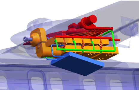
Figure 2. Nacelle-based fuel cell concept. Source: MTU.
Here we must be wise so that the system can handle 2*2MW=4MW during 5 minutes, but not longer. We can design the system so that its internal heat capacity handles this transient heat level. In the case of one engine being inoperative, this becomes 1*2 MW for 10 minutes which shall be no problem.
For the climb, maximum continuous, and cruise power levels, we must have a fuel cell system that is in balance heat-wise. It means the system shall be able to handle 2*1.4MW (which is more than 1*2 MW continuous power) during the climb, which can last up to half an hour.
The above time limits for takeoff help the thermal management system, as the lowest cooling for the heat exchangers are the low speed of takeoff (around 100kts), and the highest temperatures with reduced air density, up to 40°C at 6,000ft (the typical hot and high airport). It results in the lowest cooling from the ram air through the heat exchangers.
At higher speed (typical climb speed for a 70 seater turboprop is 170kts) and the lower air temperatures at higher flight levels, the cooling situation is considerably improved (Standard temperature at 8,000ft is 0°C and at FL250 it’s -35°C).
So the trick to a fuel cell system that is as light as possible and which has the lowest cooling drag is to size it for the long-term power levels and to rely on its internal heat capacity to handle transients. We also need to use the cool sink of the liquid hydrogen to the maximum.
We size a fuel cell system based on the above mission values in the next Corner.
Wouldn’t this be designed as a hybrid system with peak power backed by a small battery? Ie design the FC to slightly above continous demand and use excess power to charge the battery?
It seems like a good idea. But batteries have a more than magnitude lower energy density than hydrogen (it has 200 times lower energy per kilo/lb than hydrogen), so adding a battery to supply peak energy to any airborne system turns out to not work. It’s better to size the fuel cell to cope with the transient load.
I really should have asked this back when you were going through the basics of different fuels.
I have a lot of experience with land-based use of LH. And I know of most of the pros and cons.
What about using a bio-sourced LNG as a fuel?
Easier to handle, more reasonable temperatures, easy to ship and store, burns clean, and at least C neutral.
Offhand I don’t know the energy density of LNG.
Thoughts?
BIO sourced fuels (of any kind) are fine, as the plants have absorbed the CO2. But the problem is the amount of feedstock for the production, it’s insufficient for the world’s need for fuel and it would compete with food production. The inflow of energy from the Sun is enormous, especially in areas where no one lives (deserts, oceans), we just have to learn to capture it efficiently, produce transportable energy in a carrier and get it to the consumers. This is where hydrogen shines, it’s one of the best carriers of energy. And its production if you have an abundance of cheap energy is simple, water hydrolysis.
-Given the huge amount of heat a fuel cell needs to dispose of one would think it would be used to provide de-icing. There is more heat to reject than power produced. The heat power is nearly twice as much as a diesel or gasoline engine of the same power and as much as a steam engine of the same power.
-Surface cooling was tested in the Heinkel He 177, Heinkel He 100 and Focke-Wulf Fw 187. It was considered even for the Supermarine Spitfire.
-My reading of he history books (Dietmar Hermann for the Fw 187) shows that the concept was viable and did get debugged but there were concerns on ease of manufacture and battle damage tolerance.
-A Fuel Cell leading edge cooling system would not be pressurised, would remain liquid (no steam, no scavenge pumps needed and would only operate at 80C. Given the enormous power icing would not be a problem anymore.
-The issues with the Daimler Benz systems installed on actual aircraft were as follows:
He 177 thermal distortion of wing shape (used aluminium wing obviously could have been soplved). He 100 there were 24 electric scavenge pumps to return water that kept tripping out. A small supplementary radiator was needed to help control and regulate. The Fw 187 didn’t have issues. These systems worked by flashing engine heat into steam and using a centrifugal separator to divide the stream from the water and then cooling using steam in the leading edges or side panels. However in the case of an electrolyte circulating there is no steam involved and the system should be simple.
-Aerodynamically they worked very well.
Thanks, William,
yes, the heat problem of the fuel cell-based propulsion systems will require the re-discovery of surface cooling ideas and adapt these to the modern airframes material systems and production methods. Nice review of historic efforts, didn’t know some of these.
Those skin surface cooling designs were to remove the extra drag of the usual method , wing or fuselage scoops which contained the glycol radiator matrix. The Mustang and others provided a nifty solution by the ducting that in most circumstances had some residual thrust instead of drag.
Towards the end of the war the extra power developed from engines by various means sort of made the drag reduction efforts redundant.
More depth here which could provide ideas for fuel cell developments
https://www.enginehistory.org/Accessories/EvapCooling/EvapCooling1.shtml
Just 3 weeks ago, you forcefully asserted that fuel cells had no future in aircraft propulsion…
Who said anything about propulsion.
It’s as the APU they can and will be used. Heat dissapation still required
First sentence in Bjorn’s article above:
“Last week, we looked at the principal parts of a Fuel Cell-based propulsion system.”
And the result will be the same as Bjorn has said before
Forget about it and stick to APU
-As you are no doubt aware one of the biggest piston engine advances of the 1930s was the introduction of pressurised cooling circuits which raised engine water heat to about 120C or more. This allowed a big reduction in radiator size, greater engine thermal efficiency and made possible those ramjet style systems that recovered waste heat as thrust. Often referred to as the Meredith Effect in the Anglosphere after an RAF engineer who did at good descriptive paper but also a Hugo Junkers personal patent.
-The ‘evaporative cooling’ systems worked by flashing this hot 120-130 water into steam and circulating the steam in cooling panels (usually on the wing) where steams high conductivity and the latent heat of evaporation would mean little area was actually required.
-The problem with the Low Temperature Type of PEM is that the heat rejection temperature will be 80C (really has to be brought down more) not 120C. With an ambient of say 35 it will lead to a requirement for cooling area since the temperature difference will be 45 not 85. Radiator construction has definitely improved (micro capillaries) but I think it will be a challenge.
-My own view is that the internal combustion engine will persist. Modern HCCI and RCCI engines has shown that ultra lean (lambda 0.4) is commercially possible and clean and that they will be as efficient or more efficient than fuel cells. Moreover it looks like the technology will work with hydrogen as well as diesels and bifuel engines (hydrogen and jet fuel). Time will tell.
thanks alot of information
For short term emergency use, could excess LH2 be used for additional cooling?. This is similar to the use of excess fuel for reducing cylinder head temperature at high power in some old reciprocating engines.
Sure, we will explore the cooling capacity of LH2 in future Corners.
Further evidence of the extent to which hydrogen is being taken seriously in the EU:
“The largest port in Europe is set to become a major part of the hydrogen economy of the future, building out infrastructure to produce, transport, and receive the gas.
“The Rotterdam Port Authority plans to build large electrolysis units on reclaimed land and power them with new offshore wind turbines.
” The port is also preparing for hydrogen imports from around the world, studying over 100 supply opportunities to establish export chains.”
https://oilprice.com/Energy/Energy-General/Europes-Largest-Port-Plans-To-Become-A-Major-Hydrogen-Hub.html
-I attended a renewable energy expo a few weeks ago, out of personal interest, and attended some of the lectures. One of the speakers said that for Australia the best way forward for wind power was 1,2,3 hours of battery storage. He mentioned that Europe hydrogen had a place because there were typically periods of up to 6 weeks when the wind in the North Sea could be becalmed.
-I think the focus of these people is electricity generation and they were somewhat narrow minded not looking at using hydrogen for smelting of metals, calcination of cement, ammonia production and the reality that longer term storage will be needed even in Australia.
-The other big factor is that hydrogen will allow energy transport across oceans by ship either as compressed or liquid hydrogen, ammonia or electro fuels. This is probably essential for Europe.
-Europe is now keen not only for “Green Power” but energy security. Putin’s illegal act of war means that political elements of Europe (those concerned with energy security and those with ecological concerns now align).
-What worries me is that wind power is barely ready yet. Siemens Gamesa just introduced recyclable wind turbine blades, just. The industry really needed a few more years to mature its technology a little more cost effective.
–