Leeham News and Analysis
There's more to real news than a news release.

 Leeham News and Analysis
- GE testing of giant GE9X engine aims for maturity at entry into service June 30, 2025
- Bjorn’s Corner: Air Transport’s route to 2050. Part 28. June 27, 2025
- Parent agency, FAA often at odds as politics outweighs safety June 26, 2025
- Electric Flight and the Ugly Duckling June 25, 2025
- Engine makers tout “Plan A” but have “Plan B” backups in R&D June 23, 2025
Bjorn’s Corner: Sustainable Air Transport. Part 33. eVTOL batteries.
August 19, 2022, ©. Leeham News: This is a summary of article Part 33P, eVTOL batteries. This article discusses the trickiest system on an eVTOL, the battery system.
The battery system supplies the energy to the VTOL, and given today’s and tomorrow’s battery technology; it’s a tight resource that needs a lot of pampering.

Figure 1. We use graphs in the Pipistrel spare parts catalog to show the battery system of the Pipistrel Velis Electro. Source: Pipistrel and Leeham Co.
The eVTOL battery system
In the article, we go through the buildup of the battery system for the Pipistrel Velis Electro trainer, Figure 1, the only electric flying vehicle that has passed certification. It has a liquid-cooled two-pack battery system of 24.8kWh, giving the trainer 50 minutes of endurance with 10 minutes of reserves.
The system operates at a nominal 345V with a peak potential of 395V and the lowest 250V. The reason for the electric potential of 345 Volts is to lower the currents in the system, as these drive cable conductor diameter and thus mass. But the peak potential has to stay below 800V so as not to risk arching when the vehicle flies in thinner air.
Missing in Figure 1 is the High Voltage junction box that isolates and redirects power in case of a problem in the system, the power wiring, and the charging receptacle. The Battery Management System (BMS) is included in the packs. The system level Specific Energy is around 140Wh/kg.
We also detail how the battery packs (Figure 2) made by Electroflight for the Rolls Royce Racer are made.
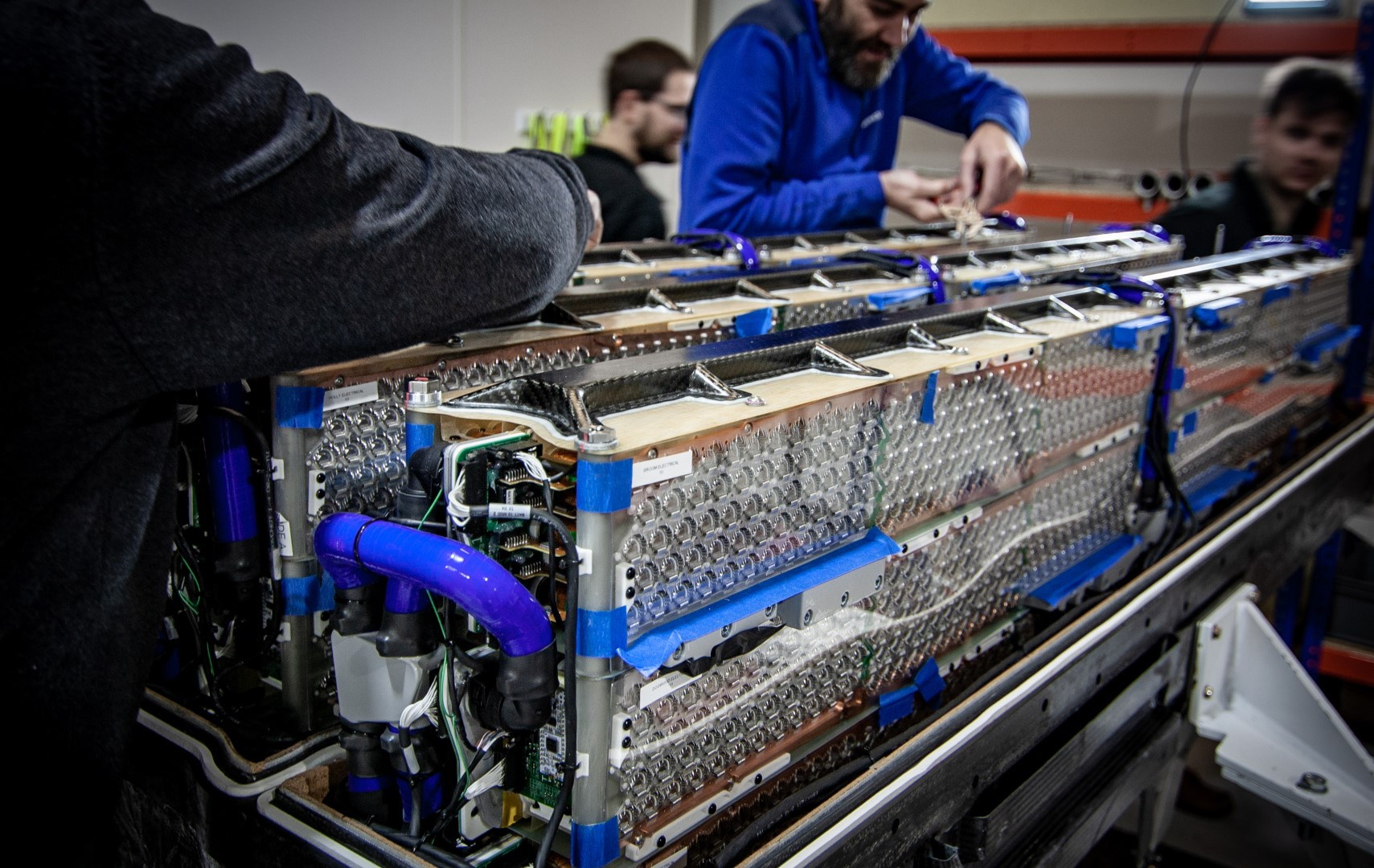
Figure 2. The modules of the Racer battery pack from Electroflight. Source: Electroflight.
Through the detailed discussion, we understand that a propulsion battery system for an eVTOL is no simple thing. The modules are highly complex, and their certification requirements are rightfully though. The energy levels are higher than a Tesla car, and there is no sidewalk to step out to should the battery start burning.
The new EASA proposed battery regulations, MOC-3 SC-VTOL, therefore, go beyond the present guideline DO-311A that was written for batteries the size of the Boeing 787 batteries. Here is the motivation for the tougher regulation:
The recent use of lithium batteries as propulsion energy storage devices in electric and hybrid aircraft increases the importance of properly addressing this hazard, due to their novel function, higher capacity, higher specific energy, and higher voltage and the lack of significant service experience in this context. Some of the most common root causes that could lead to a thermal runaway are (non-exhaustive list):
- Design and manufacturing issues
- Installation or maintenance issues
- Internal fault conditions (cell manufacturing quality issues, dendrites…)
- External abuse conditions (external short-circuit, overcharge…)
- Physical damage during storage, transportation, service, or swapping
- Heat sources (poor electrical connections, corrosion, short-circuits, arcs…)
Looking at the Electroflight modules, we can also understand why a battery system weighs and cost more than its cells. For a 100kWh system for the typical VTOL, we talk 10,000 cells, and for the larger VTOLs like Alia-250, close to 15,000 cells. Each module contains 360 cells so we need 26 modules for a 97kWh battery and 39 for a 155kWh system, partitioned into battery packs.
All the cells vary a bit in parameters and need to be managed strictly, or the battery is not safe. The cells are, therefore, managed on an individual cell level by the Battery Management System (BMS).
Through the connection of the cells, modules, and packs in series and parallel patterns, we get pack level nominal voltages of 500V to 600V with the current and power levels we need.
We will discuss how these cells react to charging and discharging, why they need management, and what cells we need to use for aeronautical systems (why Automotive cells won’t work) in next week’s Corner.
The charger and inverter might also need a cooling circuit. Don’t know if the inverter also need an output transformer to regulate Voltage and Frequency to suit the selected engine and can charge battery in windmill operation working as speedbrake/RAT. Good NASA presentation on UAM engines requirements and testing
https://aam-cms.marqui.tech/uploads/aam-portal-cms/originals/8ac41efa-4072-4a61-8fbf-41ae1ef82e3b.pdf
-The inverter won’t need an output transformer. Such devices are sometimes added to help eliminate harmonics from transistor switching when long transmission distances are involved or transmission line voltage stresses or electromagnetic interference is a concern.
-The charger should be off aircraft? (Mostly)?
-A liquid cooling system is very unwelcome. Some Battery chemistries can avoid it by operating at higher temperatures but are not common yet. Silicon Carbide transistors can operate at very high temperatures and allow smaller heat sinks.
Thanks, I know there is one on the VSCF “Variable speed Constant Frequency” system in the MD-90 with back then a very limited life on wing.
On the 787 it is a bit different and the Ham Sundstrand parts just a bit better than the Honeywell parts on the MD-90…
Managing the power distribution between the VFSGs is the bus power control unit (BPCU). The BPCU performs several functions with
* Controls bus configuration and engine health monitoring.
* Provides standby system control, generating source load management, and main and APU engine horsepower load management.
* Acts as the electrical power system communication gateway with other systems and flight deck.
EASA MOC-3 SC-VTOL (Means of Compliance issues 3, Special Condition regulation around eVTOLs) extends the testing for propulsion batteries as these are very, very dangerous (think a 10 to 20 times larger 787 battery) sitting 10 inches from you in a flying VTOL.
I have heard of no battery system that intends to pass these tests that are not liquid cooled. You have 10k to 15k cells that vary in their production quality, and you need to keep them below 60°C during discharge with up to 40 to 50 Amps. There is no practical way you can do this with air-cooled means.
-I was thinking of the cells Lilium’s chosen battery manufacturer “Customcells” was at one times asked to manufacture for Lilium. These could operate at up to 150c and thus would lend themselves to air cooling. At this time they seem to have moved to a different technology from Zenlabs, still via Customcells that I suspect will need liquid cooling but offers a better SOC curve.
-I was also thinking of the glass batteries now appearing in labs. These are in theory nonflammable and have extremely long charging lives, seemingly increasing in capacity with use and allowing high energy densities.
“It has a liquid-cooled two-pack battery system of 24.8kWh, giving the trainer 50 minutes of endurance . . . “and “. . . The system level Specific Energy is around 140kWh/kg.”
Something amiss here – is the capacity in MWh?
Thanks, it’s Wh/kg.
very good information. thank you
Bjorn, can you further elaborate on why the peak potential has to stay below 800V so as not to risk arching when the vehicle flies in thinner air?
Battery safety is very important for power vehicles, thanks for your informations