Leeham News and Analysis
There's more to real news than a news release.


Bjorn’s Corner: Blended Wing Body Airliners. Part 7

By Bjorn Fehrm
April 24, 2026, ©. Leeham News: We are making a series of articles on the Blended Wing Body (BWB) as a potentially more efficient design for passenger-carrying airliners than the classical Tube-And-Wing (TAW) configuration.
In the sixth article last week, we discussed how the drag characteristics of the BWB and a high optimal cruise altitude have consequences for the choice of engines. The thrust lapse due to altitude is higher than for Tube-And-Wing aircraft that fly about 10,000ft lower. The JetZero Z4, therefore, needs engines adapted for high climbs and cruise conditions.
This requires engines with higher specific thrust, which means lower Bypass Ratios (BPRs). This runs counter to the development trend of modern engines, which reduce specific thrust in each generation to improve propulsive efficiency and thus lower fuel burn.
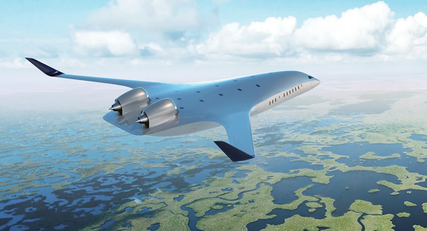
Figure 1. The JetZero Z4 BWB. Source: JetZero.
Now we look at the challenges in the structure domain for a BWB. At first glance, it should be a lighter structure than a Tube-And-Wing aircraft, as it does away with the fuselage and empennage. In reality, it’s more complicated than that.
Structures for TAW and BWBs
The structure of an airliner has two principal loads to cater for:
- The aerodynamic loads on the wings, fuselage, and empennage from gusts and flight maneuvers. To that shall be added the load of hard landings and the rare One Engine Inoperative (OEI) case.
- The pressure load on the cabin enclosure from keeping it below 8,000ft when the aircraft flies at up to 41,000ft (TAW) and 50,000ft (BWB).
The first case is the less dangerous one, as the rules prescribe a 50% margin in strength (the so-called Ultimate load) for the structure over the highest loads that experience shows airliners are subject to (the so-called Limit load).
To these loads is added a fatigue strength margin derived from a spectrum of, say, 50,000 flights for a short- to medium-haul airliner. It introduces the problem of material fatigue, in which the structural material gradually degrades its properties under long-term cyclic loads, leading to cracking in highly stressed parts.
Wing
For a TAW, the highest loads are on the wing where aerodynamic, main landing gear, and engine forces concentrate at the wing roots. The wing is, therefore, designed as a one-piece box, the wing box, to absorb the loads efficiently, Figure 2.
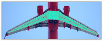
Figure 2. The wingbox (green) of a typical airliner wing. Source: Collier Aerospace.
The stresses on the wing are predominantly tension stresses on the bottom wing skins and compression on the top skins. In the occasional hard landing, the stresses reverse.
Fuselage
The fuselage cabin pressure vessel is designed as a round tube, closed by the cockpit in the forward end and the pressure bulkhead in the rear. Figure 3 shows the cabin of the Airbus A320 (the white part) with the rear bulkhead finishing the pressure part behind the rear WCs and Galleys.
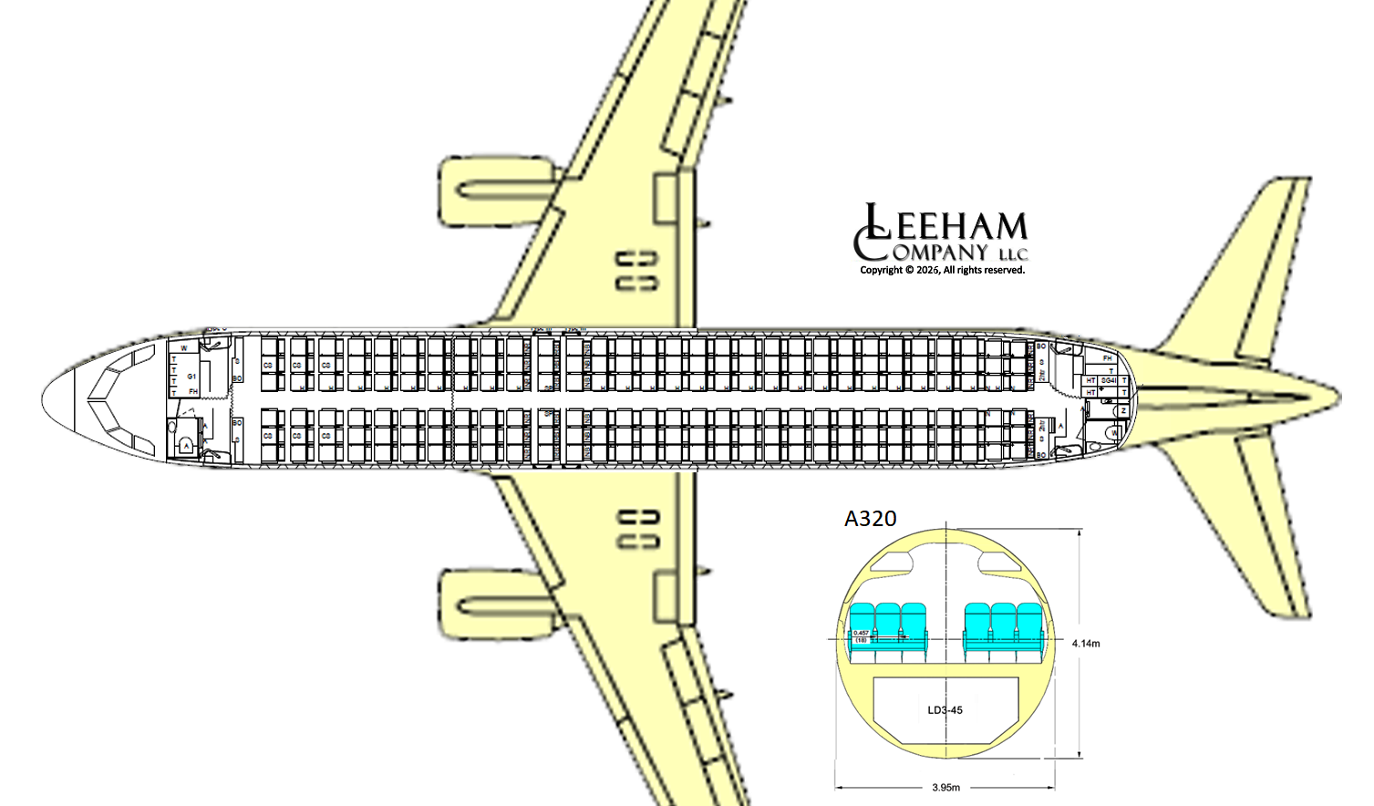
Figure 3. The pressurized part of the A320 fuselage in white color. Source: Airbus and Leeham Co.
The round shape is the most efficient to accommodate the higher pressure needed to allow the cabin to stay below 8,000ft pressure altitude when the aircraft is at over 30,000ft. The maximum pressure differential is typically 8.5 PSI/59kPa. The A320 divides the fuselage cross-section into two circular parts, closed by the cabin floor. It’s called a multi-bubble fuselage design.
The cabin pressure cycles up and down on every flight, amounting to around 2,000 pressure cycles a year for a typical short- to medium-haul airliner. Over a 25-year life cycle, this is 50,000 cycles, which poses a material fatigue problem. The laws of fatigue require that the daily stress on the wall material be much lower than what the material can endure. It’s why airliner fuselages are round or built of several round segments, joined together by the cabin floor, as in Figure 3, so that material stresses are in the direction of the skin material and do not incur bending loads on the skins.
The BWB
The BWB creates problems for the structure designer. The cabin area is not round but rather a box structure with a tapered forward section, Figure 4.
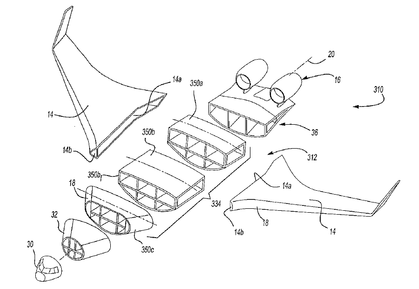
Figure 4. A principal picture from a JetZero patent around the Z4. Source: JetZero.
It should be emphasized that Figure 4 is a highly simplified illustration from a JetZero patent. It might not be the way JetZero will design the structure of the Z4. But the problem for a BWB is that the cabin area is wide, long, and flat, with a gradually narrowing front part.
A NASA study from 2005 looked into the work done by NASA and Boeing around structures for passenger-carrying BWBs and could conclude:
- Box-like pressure vessels increase material stress by over 10 times, as the in-skin-direction hoop stresses of a round pressure vessel are converted to bending forces in the box walls.
- A number of different shapes were analyzed for the pressure vessel. The most effective were several adjacent round tubes that were cut and joined by either walls or braces, with the circular sections and the walls or braces carrying stresses in their material direction, as in multi-bubble fuselages.
Figure 5 summarizes the findings, showing the required material mass per unit cabin area for different pressure vessel types.
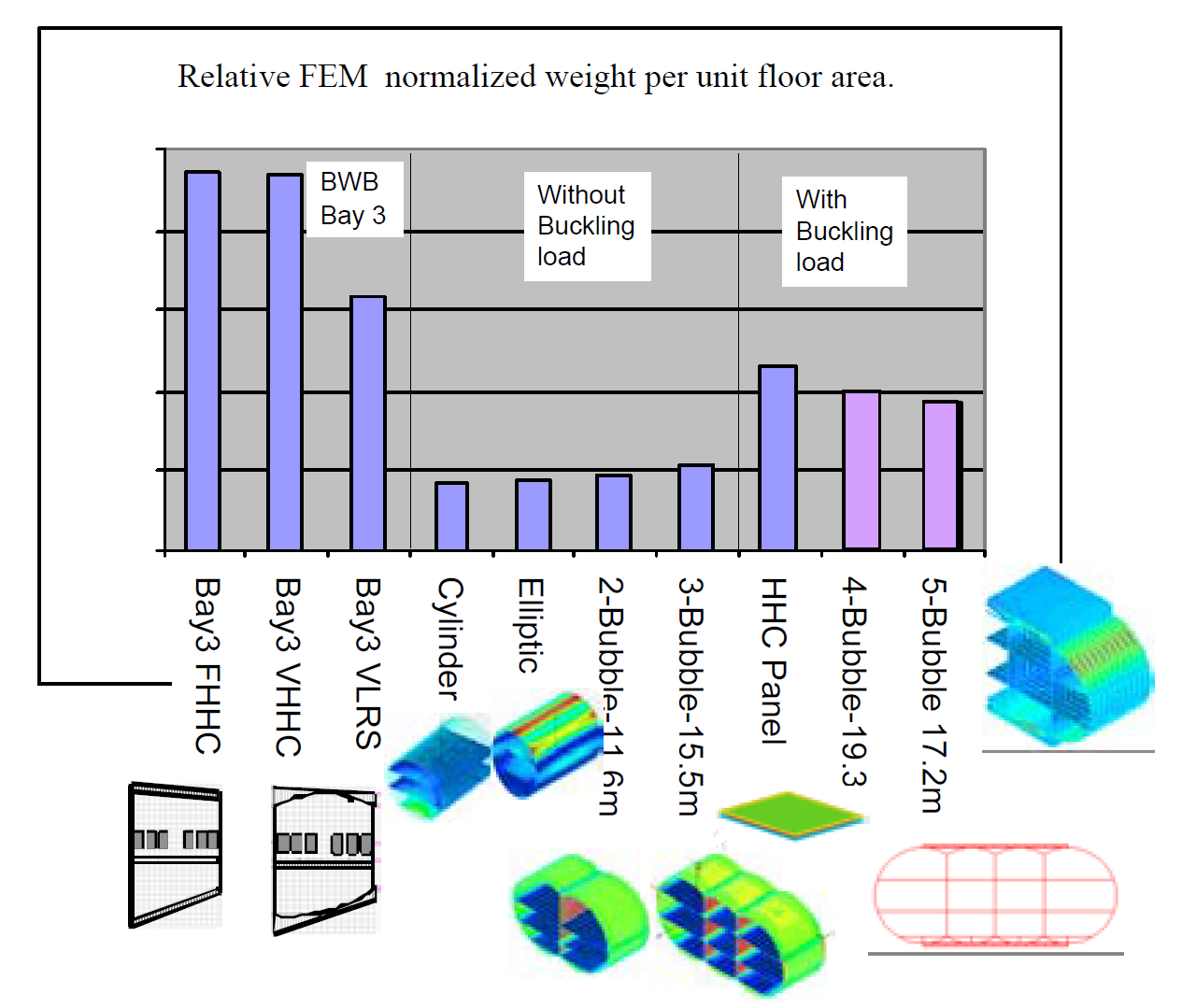
Figure 5. NASA study of structures for BWBs. Source: NASA graph from AIAA 2005-2349.
The graph shows the per-unit (ft2 or m2) weight of the pressure vessel for a TAW compared with different BWB vessel types. To the left are different BWB boxy shapes, then the TAW cylindrical or the A380 elliptical, then different semi-bubble BWB shapes.
The middle four are when the structure acts as a pure pressure vessel; the left and right three are when thicker outer skins are required to carry wing loads in addition to the pressure loads. The requirement to be both a pressure vessel and a central part of a wingbox complicates the BWB design.
Conclusion
For a TAW airliner, the roles of wingbox and cabin pressure vessel are divided, allowing optimized stress propagation in the materials for each structure’s role.
The BWB has a troublesome cabin shape complicated by also serving as a wingbox, which demands a clever structural concept to not be heavy. We are not saying that the JetZero Z4 BWB will be structurally disadvantaged compared with a TAW design. The subject is too complex, and we know too little about JetZero’s way to solve the problem.
What one can say is that it will be a tricky challenge to devise an effective structural concept that secures regulatory certification, not least because there is no prior certification or in-service experience with structures for passenger-carrying BWBs.