Leeham News and Analysis
There's more to real news than a news release.


Bjorn’s Corner: Largest navigation change since radar, Part 6
July 20, 2018, ©. Leeham News: Last week we discussed how a TCAS (Traffic Collision Avoidance System) works and how ADS-B will improve the system.
Now we discuss other areas of aircraft navigation and separation which are enabled when all players have ADS-B and transmit their 3D position and where they are going.
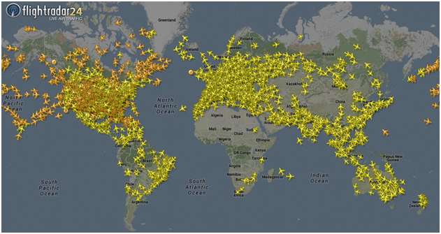
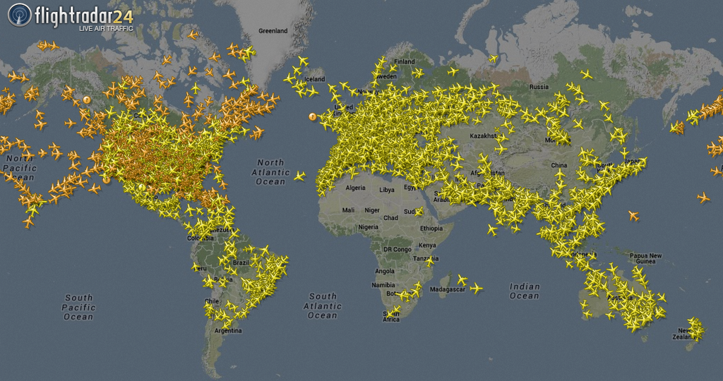
Figure 1. Air traffic is getting denser and denser. Source: flightradar24.
Bjorn’s Corner: Largest navigation change since radar, Part 5

By Bjorn Fehrm
July 13, 2018, ©. Leeham News: Last week we discussed ADS-B in capabilities and how the US second channel at 978MHz brings the bandwidth for many useful services.
Before we discuss what improvements in navigation ADS-B will bring long-term, let’s sidetrack to describe the present Traffic Collision Avoidance System (TCAS) and why it’s eventual replacement with ADS-B will improve air safety further.
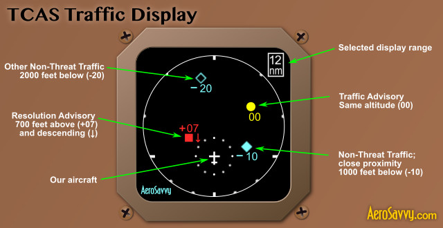
Figure 1. A TCAS II display with warnings and advisories. Source: AeroSavvy.com
Bjorn’s Corner: Largest navigation change since radar, Part 4
By Bjorn Fehrm
July 06, 2018, ©. Leeham News: Last week we discussed the different forms of ADS-B out and the reason FAA went for a second channel for the US ADS-B.
We also discussed the basic ADS-B in function, Traffic (TIS-B). Now we discuss the added functionality of the ADS-B in on 978MHz, the UAT link.
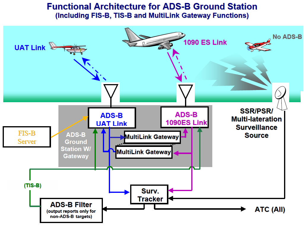
Figure 1. The functions of the US ADS-B ground stations. Source: FAA
Bjorn’s Corner: Largest navigation change since radar, Part 3
By Bjorn Fehrm
June 29, 2018, ©. Leeham News: Last week we explained ADS-B out, the mandatory equipment needed from 2020 for flying in the US Airspace where a C-type transponder is needed today.
Now we continue with describing the ADS-B in, the listening capability of the system, which is nonmandatory. It offers exciting possibilities, however.
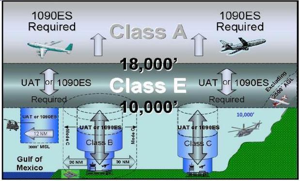
Figure 1. The ADS-B is mandatory in most US airspace areas. Source: FAA
Bjorn’s Corner: Largest navigation change since radar, Part 2
June 22, 2018, ©. Leeham News: Last week we started a series of Corners that deal with the largest navigation change since VOR and Radar was introduced after the Second World War.
It’s about leaving radars and transponders to keep track of where aircraft are, letting an ADS-B transmitter/receiver in the aircraft take over this role.
Figure 1. The ADS-B is mandatory in most US airspaces. Source: FAA
Bjorn’s Corner: Largest navigation change since radar
Bjorn Fehrm
June 15, 2018, ©. Leeham News: The worldwide aviation is heading for its largest navigation change since VOR and Radar was introduced after the Second World War.
When scheduled airline traffic started in the late 1920s, navigation was with maps and when the weather was bad, through Low-Frequency Radio beacons. Then the VOR and Radar were introduced. Now we will replace these as well.
Bjorn’s Corner: Aircraft stability, Part 9
By Bjorn Fehrm
June 8, 2018, ©. Leeham News: In the last Corner we discussed how a pilot uses the advanced Automatic Flight Control System (AFCS) on modern high-end business jets and airliners.
Now we will discuss what separates the high-end (and expensive) systems from the less capable we described before. It’s about flying difficult routes which contain demanding takeoffs and approaches.
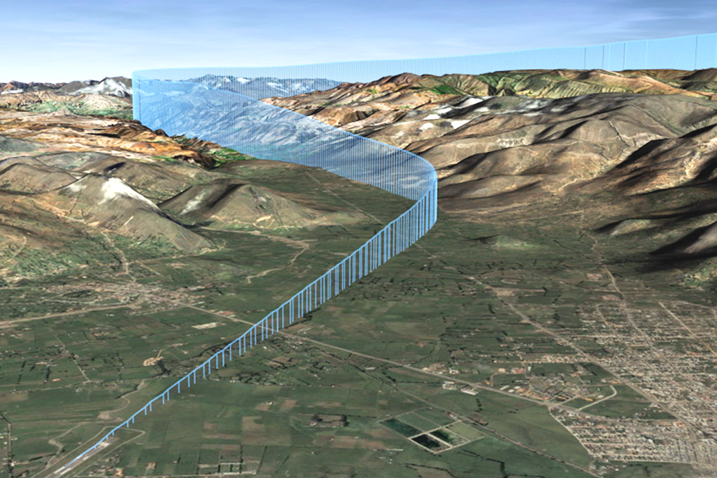
Figure 1. A challenging approach where RNP based navigation is needed. Source: Wikipedia.
Bjorn’s Corner: Aircraft stability, Part 8
By Bjorn Fehrm.
June 1, 2018, ©. Leeham News: In the last Corner, we discussed the how the Flight Management System (FMS) is the part which calls the shots in a high-end autopilot (or Automatic Flight Control System, AFCS, as it’s called in high-end business jets and airliners).
Now we will dig deeper into what happens once the FMS has figured out how we shall follow a route.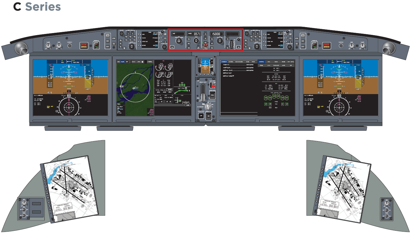
Figure 1. The Automatic Flight Control System (AFCS) panel of the CSeries (surrounded with red). Source: Bombardier. Read more
Bjorn’s Corner: Aircraft stability, Part 7
By Bjorn Fehrm
May 25, 2018, ©. Leeham News: In the last Corner we discussed the autopilots one finds in Airliners and high-end Business jets. We looked at how the autopilot was part of the larger Automatic Flight Control System (AFCS) in Bombardier’s CSeries.
To understand how such an advanced system works, we need to go through the different parts of the system and understand their role when the aircraft is flown by the autopilot. We will start with the Flight Management System (FMS) this week.
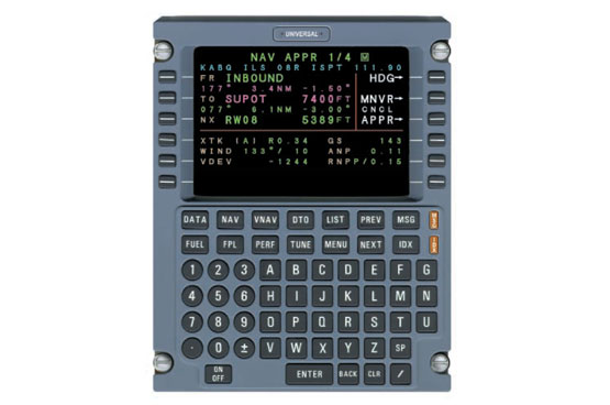
Figure 1. The flight deck part of a classical FMS (Flight Management System). Source: Esterline.
Bjorn’s Corner: Aircraft stability, Part 6
By Bjorn Fehrm.
May 18, 2018, ©. Leeham News: In the last Corner we discussed the autopilots one finds in Turboprops and entry-level Business jets. Our example was the autopilot for the Garmin G1000 integrated flight deck.
Now we will step up to the airliner level. We will look at the autopilot and its supporting avionics for the Bombardier CSeries. This is a modern, state of the art system, and a good example of the autopilots for an Airliner or top of the line Business jet.
Figure 1. The CSeries flight deck. I have marked the autopilot panel with a red border. Source: Bombardier.