Leeham News and Analysis
There's more to real news than a news release.


Bjorn’s Corner; Turbofan engine challenges, Part 7

By Bjorn Fehrm
December 16, 2016, ©. Leeham Co: After the turbine comes the engine’s exhaust system. This is where the thrust characteristics of the engine are formed. It is also the environment that defines the back pressure for the fan and turbines. It’s therefore more high-tech than one thinks.
For the very high bypass airliner engines of tomorrow, the common fixed bypass exhaust of today (Station 18 in Figure 1) will not be acceptable. Variable exhaust areas will have to be introduced.
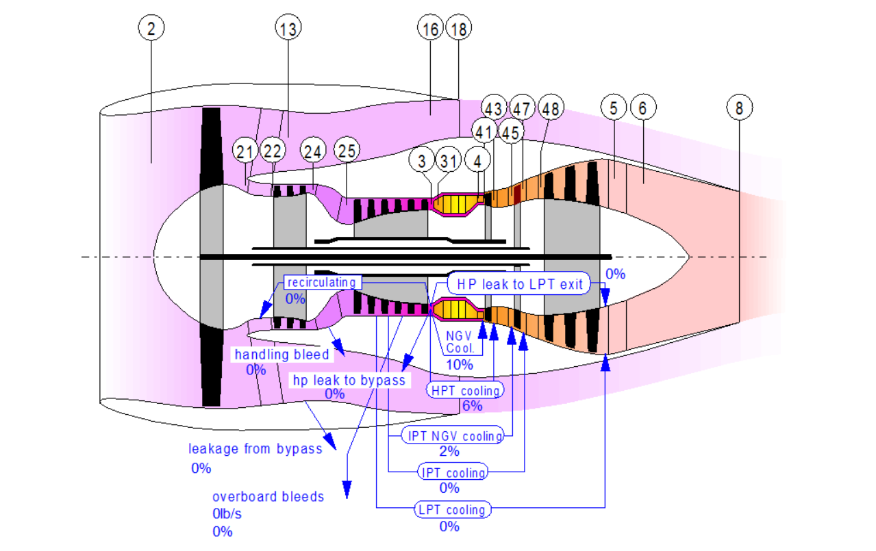
Figure 1. GasTurb principal representation of a three shaft turbofan like our reference Rolls-Royce Trent XWB. Source: GasTurb.
On engines that function in high supersonic speed, it gets really complex. Not only is the exhaust area variable, it must have a dual variation exhaust, a so-called Con-Di nozzle.
Engine exhausts
The exhaust of an aircraft turbofan is called a nozzle. The nozzle is designed to give the air/exhaust gas leaving the engine the right speed and pressure. Figure 2 gives the GasTurb-simulated data for the different core stations for our reference engine, the Rolls-Royce Trent XWB 84klbf. The station positions can be found in Figure 1.
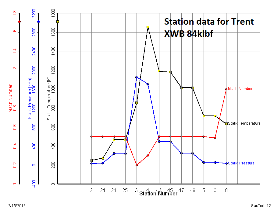
Figure 2. The speed, pressures and temperatures through the engine. Source: Leeham Co.
Look at the speed graph for the air passing through the engine. It is kept at or below M0.5 all the way until it comes to the exhaust nozzle, Station 8. As the aircraft (the Airbus A350) flies at M0.85, having the core exhausts leave the engine at M0.5 would mean it would brake the aircraft rather than delivering thrust.
The core nozzle is therefore converging to an exit area that will take the gas to an exit speed close to or at Mach 1 dependent on throttle position. The picture is from the Top of Climb phase, so the throttle is close to 100%. Therefore, the nozzle exit speed is Mach 1.0.
The actual gas speed corresponding to Mach 1 is dependent on the gas temperature. Here, it has a temperature of 620K/450°C and therefore a velocity of 500m/s. The Mach 1 speed comes from the fact that a simple convergent nozzle can only accelerate gases up to Mach 1. To bring them to higher Mach numbers, we need a convergent-divergent nozzle that one sees on military engines designed for Mach 2 flight, Figure 3.
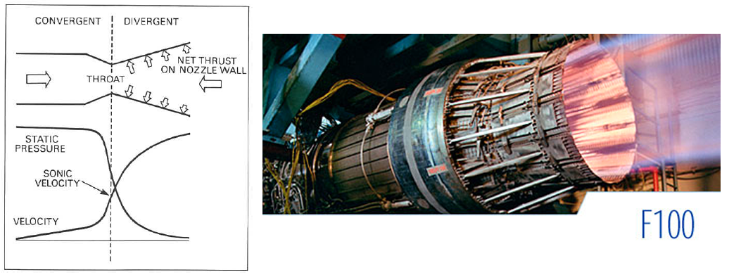
Figure 3. Convergent-Divergent nozzle (Con-Di) as used on the Pratt & Whitney (PW) F100 engine for the Boeing F15. Source: Rolls-Royce and PW.
For civil subsonic airliners, a convergent nozzle works fine. The overspeed that can be generated is ok for subsonic flight.
Nozzles for civil airliner engines can be divided in two types, separated or mixed, Figure 4.
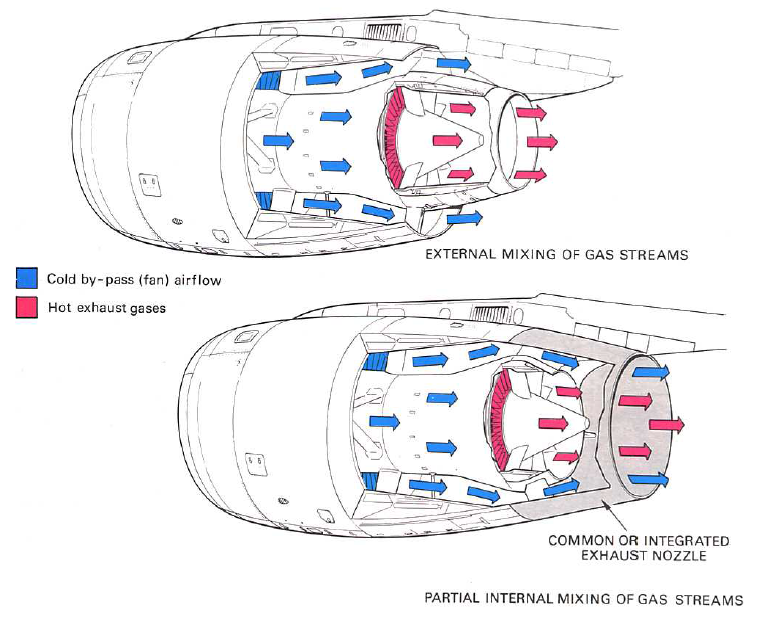
Figure 4. Separate by-pass/core or mixed nozzles for high bypass turbofans. Source: Rolls-Royce “The Jet Engine.”
Mixed nozzles give a small efficiency gain as the hot core gases heats up the cold by-pass stream. It makes the nacelle longer and heavier, however, and is therefore seldom used. The most common example of the use of the two types is for the Airbus A320 engines. The CFM56 has the common separate cold and hot nozzles whereas the Pratt & Whitney V2500 has a mixed nozzle, Figure 5.
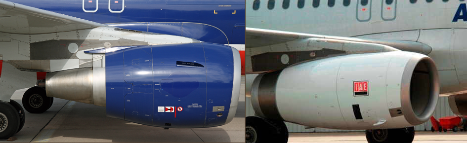
Figure 5. Separate hot/cold and mixed nozzles on CFM56 and PW V2500 for Airbus A320. Source: Wikipedia.
The cold nozzle for the by-pass stream sets the back pressure for the engine’s fan. As the by-pass ratio grows over 10:1 the widely different environment for the fan at take-off/landing and cruise starts to be troublesome. The backpressure differs so much that the fan can run into non-stable conditions under low speed/low power conditions.
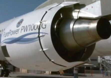
Figure 6. Nacelle for PW Geared Turbofan with variable cold nozzle open. Source: PW.
A way to handle that is to use a variable exhaust area by-pass nozzle, like the one seen for the PW Geared Turbo Fan in Figure 6.
The figure shows an early test nacelle with the movable nozzle part moved back to increase the nozzle area and thereby decrease the back pressure for take-off and landing. The production engine stability margins turned out better than predicted. The variable nozzle could thereby be skipped for production nacelles.
As the by-pass ratio grows much above 10 (the PW GTF has a BPR of 12:1 in the largest fan version), we will see the variable cold nozzle nacelles reappear. The alternative is variable pitch fans as used for the future Rolls-Royce Ultrafan.
Its amazing any of it works let alone above Mach 1 without rockets.
Exits seems simple at subsonic turbofans but they have a large influence on the working of the engine. The fixed exit is compromise between cruise efficiency and being good enough for take-off and climb.
Hi Björn,
You correctly pointed out that the local speed of sound (c) is function of temperature. This rule applies to the entire gaspath. As the air temperature increases so does the value of c (= M1.0) become higher.
This changes slightly the dynamics of sonic phenomena in gas turbine airflows. The most puzzling expression of this rule is the seemingly strange evolution of the airflow and its visible shockwaves in a supersonic afterburner exhaust (https://en.m.wikipedia.org/wiki/Shock_diamond)
I use a very simple approximation c=20.1xSQRT(T*), where T* is the TAT in °Kelvin.
Thanks Ferenc, the Mach diamonds are nice and I will remember the rule of thumb. The result is speed of sound in m/s.
Will A320XLR benefit from variable area nozzle on GTF engine, as it needs more takeoff thrust and longer time in cruise? Also theoretical A220-500 benefit as to get more power at takeoff for higher MTOW?