Leeham News and Analysis
There's more to real news than a news release.

Fundamentals of airliner performance, Part 6; The engine
By Bjorn Fehrm
19 Jan 2015: There is a lot written about the fundamentals of how aircraft fly. It is something that fascinates people and it generates a high level of understanding of these fundamentals. The same is not true for the airline turbofan engines in use today; their detailed function remains a bit of black art.
![]() To some extent this might be because what is exiting in the engines (the thrust) is generated behind closed doors. The only visible part of the process is a rotating fan face and sometimes a slight miss-colored exhaust out the other way. There is also at takeoff a funny buzzing sound interspersed with the general engine noise. Apart from that, the most that one sees is a round nacelle and that is it.
To some extent this might be because what is exiting in the engines (the thrust) is generated behind closed doors. The only visible part of the process is a rotating fan face and sometimes a slight miss-colored exhaust out the other way. There is also at takeoff a funny buzzing sound interspersed with the general engine noise. Apart from that, the most that one sees is a round nacelle and that is it.
If one opens the lid of a modern turbofan, one finds a virtual fireworks of advanced technology. Aerodynamically engines cover a larger envelop than the aircraft it sits on. They go to full supersonic flow in the fan. The aerodynamics in the compressors and turbines are 3D shaped to a level which is not found on the aircraft. For reasons of manufacture, the tube section of the fuselage does not have Coca-Cola bottle-type waist, etc.. The technology around emission control when burning fuel efficiently is reaction chemistry at the highest level and finally the fact the turbines don’t melt from working in gasses almost double the temperature of their melting point is mind boggling.
Modern airliner turbofans are at least as exciting as the aircraft they serve, if not more so. As we’ve seen with the Boeing 787 and 747-8, the 737 MAX, the Airbus A350, A330neo, A320neo and potentially the A380neo, engines drive the airplane development; new airframe design might add 5-10% of efficiency—new engines add 10%-20%.
Here is a closer description of these technological wonders. We describe engines with the help of CFM’s new LEAP engine.
LEAPing from the CFM56 to new technology
In Part 2 or our series we described the LEAP-1B engine of the Boeing 737 MAX 8 on a general level. We will now dive deeper into the LEAP-1B and compare it to the engine it replaces, the CFM56-7B, used on the 737NG.
The company behind the engines, CFM International, a joint venture of GE Aviation and Snecma of Safran, is the world’s dominant manufacturer of engines for airliners with more than 27,400 engines sold and in service. In preparation for this part of our series, CFM described its philosophy when designing the heir to the world’s most successful aero engine, the CFM56. We were especially interested in how CFM would combine a 15% efficiency improvement with the reliability and maintainability levels that a sequel to a CFM56 would imply. Details are below.
To make it possible to follow the evolution from the CFM56-7 to the LEAP-1B and understand the design challenges involved, we have built a model of the LEAP in our engine modeling tool, GasTurb12 of GasTurb GmbH of Aachen Germany (http://gasturb.de/index.html). It is very powerful engine simulator and has excellent visualization graphics which we will use to try and understand the technology choices that CFM has used to produce the LEAP.
It shall be pointed out that these simulations are carried out with our own estimation of values for LEAP-1B in GasTurb. CFM has not provided any more information than what is to be found in their official communication and Power Points (as should be expected at this point of the program). We do these simulations to further the overall understanding of a state of the art engine like the LEAP and how the different parameters change during normal use, and not in order to reveal any of CFM’s proprietary design data (which we can’t as we don’t have it).
Turbofans and how they work
We will now go through the evolution of the LEAP-1B and learn how turbofans are specified, how they work and how CFM managed to improve the efficiency with 15% while retaining the reliability of the CFM56. The engine was briefly described in Part 2 of our Series. We will now dive deeper to see what parameters are critical and how CFM used its technology leadership in many areas to realize the engine with principally the same base architecture as CFM56. But before we go into the engine, let’s look at the requirements Boeing would have for a new engine for the 737 MAX.
MAX requirements
To understand how an engine like the LEAP gets designed, we will follow the process from Boeing’s decision to do the 737 MAX series until design freeze of aircraft and engine. When Boeing decided to do a 737 MAX instead of a new single aisle aircraft, CFM had designed the LEAP-1A for the A320neo and the LEAP-1C for the COMAC C919. The requirements on the engine from A320, C919 and 737 are not the same. For instance, the needed maximum TakeOff thrust is 33klbf (lb force which we write as lbf) for A320 and 28klbf for the 737 MAX. Adapting the 737 engine from the A320 would have produced a suboptimal engine as the thrust requirements for the 737 are around 10% less than for the A320 series. Keeping the core would have meant the core was dimensioned for driving a fan to generate 33klbf of thrust and not 28klbf. The result is a loss in efficiency. The core should be the minimum required to do the job to make for an efficient engine.
The LEAP-1B is therefore a design 100% adapted to the requirements of the 737 MAX.
Here the important requirement points on a civil airliner turbofan engine:
Top of climb thrust
For many aircraft, the thrust needed to get to the initial cruise altitude is the most demanding requirement flow-wise for the engine and therefore it determines the aerodynamic paths (the efficient throughput of the air mass as described in Part 2) and thereby the size of the engine. Our airplane model shows the LEAP should produce around 6,000lbf at the last part of the climb to reach initial FL320-330 with an acceptable minimum climb speed for the heaviest member of the MAX family, the 88 tonnes MAX 9 (an engine is sized by the most demanding member of the family, then derated to serve lighter and smaller members). Ideally that thrust level shall be flat-rated to 15°C (27°) over normal or ISA temperatures. At FL320 this would mean 15°C over -48°C (-33°C or -28°F).
TakeOff thrust
For a two- engine aircraft, which loses 50% of its power if an engine goes inoperative at takeoff in contrast to a four engined aircraft which loses only 25%, the takeoff requirements can be more demanding then the top-of-climb requirements. It is normally not the static thrust, i.e. when the aircraft is lining up at end of the runway, which is the problem. It then has both engines intact and has plenty of power. The most critical demand on the engine is when one is going inoperative directly after lift-off. The requirement is then that the aircraft shall be able to climb with a minimum 2.4% at the so-called safety speed, V2. For a MAX 9 at Max Takeoff Weight it would be around 145kts and the required thrust would be approximately 22.000lbf on the remaining engine. For our six tonnes lighter MAX 8, the requirement would be around 20,500 lbf at a speed of 140kts.
Flat rating thrust
Most engines are specified to maintain their takeoff and climb performance to ISA +15°C. Often the most stressing point for the engine temperature wise is therefore start from hot airports at the max rated thrust and max rated temperature. When we simulate the known and assumed values of the LEAP-1B, the V2 demand of 22.000 lbf at ISA +15°C comes out as the most challenging condition, it sizes the engine core processes that we need to drive the fan to produce 90% of the 22,000 lbf thrust. The remaining 10% thrust is a rest product from the core while producing the shaft horsepower for our fan.
Cruise thrust
The cruise thrust requirements are much lower. Still the engine has to work hard to satisfy these. At average cruise weight the MAX 9 needs 4,900 lbf and the MAX 8 4,500 lbf to overcome the aircraft drag at 35,000 feet and M 0.8. The fan requires the low pressure turbine to produce 9,800 hp to produce this thrust for the MAX9 and 9,200 hp for the MAX 8. This means we need two shaft hp to produce one lbf of thrust at cruise and we only needed 1.36 hp (total 30,000 hp) to produce the 22,000 lbf of thrust at the denser air at sea level. The engine is only producing less than 5,000 lbf but is still working hard aerodynamically and spinning at around 90% of full rpm to produce the thrust we need at cruise.
Specific fuel consumption
The cost of producing these 4,900 lbf (MAX 9) or 4,500 lbf (MAX 8) is measured in how much fuel is consumed per hour to produce one lb force (lbf) of thrust. At ground level and takeoff, the cost is around 0.3 lb/lbf/hr and at cruise around 0.6-0.65 for the present CFM56 engines. For the LEAP, CFM managed to reduce this a full 15% to around 0.53-0.56 lb/lbf/hr. The range at cruise is deliberate, it depends on many factors.
When engine manufacturers give the Thrust Specific Fuel Consumption, TSFC, one has to be careful with at what condition it is given. Many times the values of TSFC, e.g. as given in the ICAO Emission Databank (only takeoff, initial climb and landing TSFC, not cruise), are test stand TSFC with no nacelle losses and no power offtake for driving hydraulics for flight controls, electrical generators or bleed air for the cabin air conditioning . This increases the TSFC with 7-8% and therefore values that seem extremely good (low 0.5 for existing engines) are most of the time from test stands with no service functions to the aircraft included. Our simulations show that LEAP-1 achieves state-of-the-art values for this size of aero engines (it is harder to make a smaller engine efficient as gap tolerances don’t scale with smaller dimensions of compressor or turbine blades).
LEAP design choices
How did CFM achieve the 15% reduction while maintaining the CFM56 reliability level? To begin this analysis, let’s start with the question we put to CFM through their director of Strategic Communication, Jamie Jewell.
- In Power Points around the LEAP, it is described as having lower overall pressure ratio than GEnx-1. It would mean lower static takeoff ratio than 47 (which is the ICAO Annex 16 ratio you give for the highest revving GEnx-1). Is this correct?
A: Narrowbody aircraft have different design objectives than widebody aircraft because of high cyclic operation, which can be up to 6-8 flights per day. The expectation for LEAP is 20,000 cycles on wing, first run, in order to achieve low maintenance cost. The message of the chart is that the cycle design and temperatures for LEAP have been selected for the right balance of performance and operating cost. High cycle temperatures resulting from high operating pressure ratio could drive down time on wing and increase maintenance cost.
- When you state the LEAP will have the same reliability as the CFM56, do you mean the same cycle limits, same EGT margins or both?
A: Reliability in this sense means the operational metrics in terms of departure reliability, delays and cancellation rate, in flight shutdown rate.
- Will this be from launch or will there be a maturity curve that you will follow?
A: The goal is from launch. Significant advance maturation work is being conducted, including 40,000 cycles of testing prior to EIS.
- Will the maintenance provision per flight hour be the same as well? if not, above or below?
A: The maintenance cost per hour target for LEAP is expected to be comparable to the CFM56 family over its lifetime.
- What variants of power by the hour agreements will you offer your customers?
A: CFM is offering three levels of aftermarket support for LEAP: full risk transfer through a long-term rate-per-flight hour (RPFH) agreement, under the terms of which CFM guarantees the maintenance costs; Material Service Agreements (MSA); and Time & Materials. Our goal is to provide our customers with more flexibility through customized agreements and an open network (the details of which we have not yet finalized).
LEAP implementation
In essence this mean the LEAP is a true heir to the CFM56 with the same targets for reliability and maintainability. We will now look closer at how this is achieved. We reuse the picture from Part 2 but dive deeper on each point this time (as before, this is a picture of the LEAP-1A or C but the principal technologies are the same for LEAP-1B):
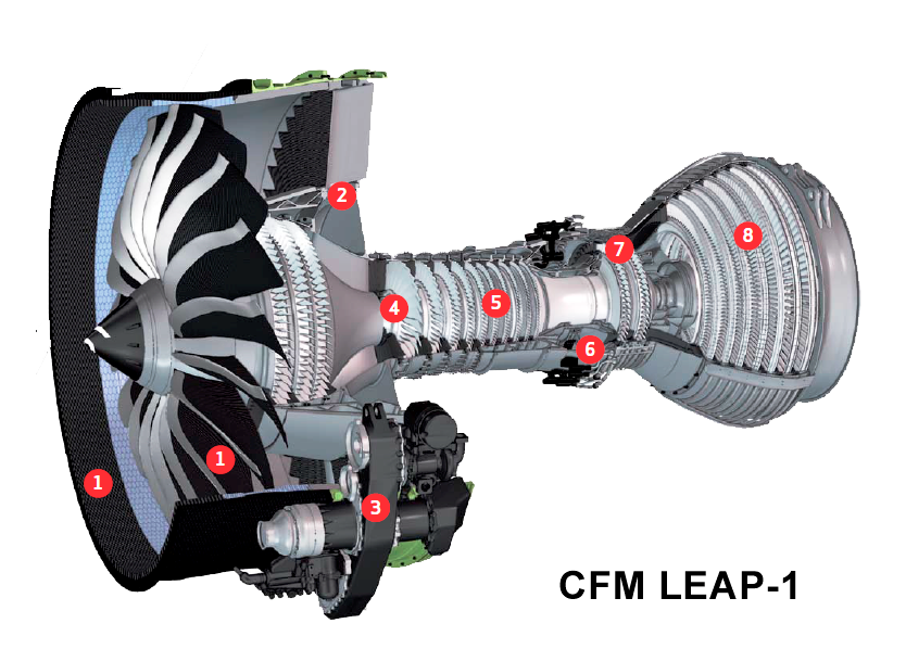
Figure 1. LEAP-1 engine cut through showing the main areas of interest. Source: CFM.
No 1 marks the fan and fan case. GE is the world leader in CFRP-based fans (first with GE90) and fan cases (first with GEnx). LEAP is now taking this technology further. The GE90 and GEnx blades are hand-laid up from CFRP prepreg cloth. Snecma, which has responsibility for the fan and low pressure parts in CFM, has formed a joint venture, Albany Engineered Composites Inc. (AEC, Rochester, N.H.) with one of US high tech weaving companies, Albany International. AEC has the technology to weave the Carbon fibers into a 3D mesh which when placed in a form get soaked in injected resin.

Figure 2. Albany Engineering Composites, AEC, resin infusion fan blade form with the interlocked weaved carbon fiber in place. Source: AEC
With this technique, fibers can be woven in an interlocking manner eliminating any risk of delamination associated with the discrete layers of prepreg in conventional blade layup. The technique can also be more automated, necessary for the high volumes that the LEAP will be produced in.
This process also gives very exact control of the blades properties like directional stiffness of the different parts and we understand that Snecma is using this to have the blades form themselves according to their working condition. A modern fan is a very advanced piece aerodynamically. Its tips are supersonic, the middle part has transonic aerodynamics and the inner part has subsonic aero. This requires different aerodynamic forms, from thin and pointy to blunt and round. In all 3D woven resin infused blade ensures a very exact blade with high efficiency and low weight. AEC is also producing the fan case in the same way, first forming the weave and then infusing the resin.
Right after the fan come the booster compressor. As it sits on the same diameter as the fan’s inner part it has subsonic aerodynamics and a low speed through the air. The pressure gain is therefore low, on the level of the fans average pressure ratio of around 1.4-1.5. Conversion efficiency, shaft hp to pressure gain, can still be as high as the fans efficiency using today’s advanced 3D aerodynamics, above 90%.
No 2 denotes the variable bleed ports on the outer part of the swan neck duct between booster and compressor. The fan will ingest debris like sand from the runway. It is important to keep that away from the fine dimension of gaps and seals in the core. CFM uses several techniques to ensure this:
– the spinner form throws most debris past the core entry, into the bypass.
– The small particles that do enter the core swan neck will then slide on the outer wall of the duct due to its curvature where the engine control computer, the FADEC, can angle the handling bleed doors slightly open to catch the particles that got ingested and route these to the bypass duct. This technique has been proven on the GE90 operating in sandy environments.
No3. Snecma is also responsible for the gearbox with accessories. It is mounted on the fan case to ease service access and slung to the side to maximize ground clearance.
No 4. The passing point of the responsibility in the core from Snecma to GE Aviation, where the booster swan neck leads into the High Pressure Compressor, HPC.
No 5. The high pressure compressor, HPC. It takes the air from a pressure raise of around 2 and raises that to above 40 before the air passes into the combustor. GE Aviation is known in the industry to be the masters of efficient high pressure rate compressors. Our simulations for cruise suggests the HPC for the MAX8 consumes around 9,500 hp to do that with a conversion efficiency (shaft energy to compressed air energy) of well above 90%. At its peak operating point it can raise the pressure 22 times, most of the time it is operating around 20 times however.
One of the effects of this high compression is that the air gets hot, at ground level and hot take-offs the HPC exit temperature can be a limiting factor. Our simulations with GasTurb suggest the HPC exit would be at around 700°C or 1,200°F. The last stages of the HPC is therefore made with heat resistant nickel based alloys whereas the early stages are made of Titanium. They can be machined in on piece (nickel based alloys are not easy to machine), so-called BLISKs, giving both aerodynamic (leakage) as well as manufacturing advantages.
At this point it can be instructive to understand that most values in a turbofan engine vary with the demanded thrust. Figure 3 is showing a diagram from a GasTurb simulation of the LEAP-1B at average cruise height. It shows what happens with specific fuel consumption (SFC), overall pressure ratio (OPR) and by-pass ratio (BPR) when the engine goes from en-route climb (5,300 lbf) to cruise (4,500 lbf) to flight idle (probably around 1,000 lbf).
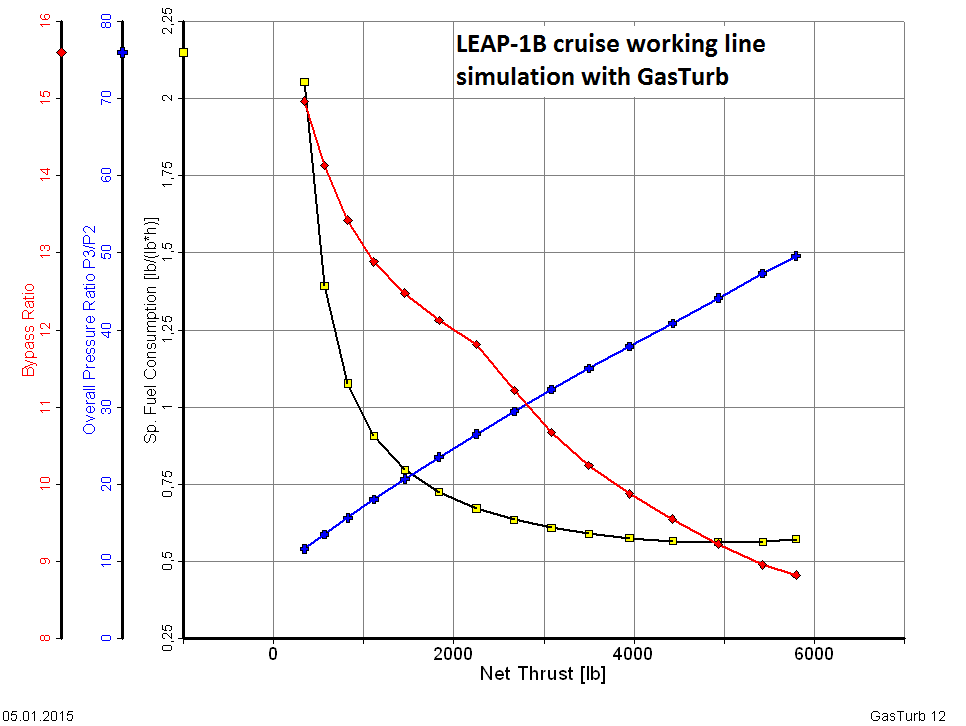
Figure 3. Simulation of LEAP-1B working line with GasTurb12. Source: GasTurb and Leeham Co.
The diagram shows several interesting aspects of turbofan design:
TSFC: this varies with every thrust setting of the engine, important is that the TSFC “bucket” has its minimum at cruise thrust (between 4,000-5,000 lbf).
OPR: The overall pressure ratio of an engine is a function of its rpm, high thrust = high rpm = high OPR. The important area is once again cruise where OPR would be around 40, a good value and one of the corner-stones in the high efficiency of the LEAP.
BPR: Finally the By Pass Ratio, BPR, is varying from 8.7 to 13-15 at flight idle. BPR is strongly coupled to how hard the engine is working, the higher thrust, the more air through the core (to generate shaft hp) and lower BPR. This is why higher rated members of an engine family always have lower typical BPR. The kink in the BPR is from the on-set of a handling bleed through the variable bleed ports after the booster. At low load the HPC gets to aggressively feed by the booster and therefore excess air is bleed into the bypass channel from (in our simulation) 2,200 lbf thrust. Should this not be done the HPC early stages would stall.
No6. On our journey through the engine the next station is the combustor. One of the problems with high pressure ratios in turbofans is that this creates high levels of NOx emissions. GE has developed a lean burn two-zone combustor series called TAPS to master. LEAP is using the latest incarnation of this technology, TAPS II. The TAPS combustor also has a very uniform distribution of the heat in the exit gasses to avoid hot spots in the combustor nozzle and the first high pressure turbine stage.
No 7. LEAP divides the driving of the high pressure compressor over two turbine stages instead of one for the CFM56. This is necessary as the work done in the HPC has doubled, from maximum pressure ratio 11 for the CFM56 to 22 for LEAP. To create shaft hp efficiently with the smallest core, the gasses entering the turbines shall be hot and at high pressure. State-of-the-art right now (GEnx-1B75 ) is 1,700°C or 3,150°F turbine entry temperature and about 55 in pressure raise from inlet to first turbine. As stated by CFM, LEAP has another optimization philosophy than GEnx. We have assumed around 1,550°C and a pressure rise of around 50 at the most extreme working point.
To withstand such temperatures, the turbine section requires cooling and quite a lot of it for the first stages. At the toughest operating point, which we found to be one engine out at V2 on a hot day, the turbines needs over 20% of the air produced by the compressors for cooling. This cooling air is consistently taken from the lowest compression level possible in the engine, from fan, booster, compressors and even combustor; the pressure need to be high enough to secure positive circulation in the cooling object at all conditions but not more, any more pressure and the air is hotter than needed (worse cooling result) and more engine work has been invested in creating the cooling air than necessary.
A turbofan is therefore riddled with cooling air off-takes. The CFM56 has about 10, from after the fan for nacelle and aircraft bleed air cooling to the HPT being cooled with air from the combustors peripheral airflow. The highest cooling demands are for critical flight cases like takeoff or one engine flight. For cruise, the demands are lower. It is therefore attractive to regulate the cooling air for the different load cases. Easiest is to regulate the air to the stator side but the latest airliner engines have also regulated the air to the turbine rotors. To check what regulated turbine cooling would give, we halved the turbine cooling air in our simulator, which gains the engine about 1% in TSFC.
Better still is to use materials that require very little cooling such as Ceramic Matrix Composites, CMC. GE is a leader in the use of CMC for turbine engines. GE has deployed it in their stationary gas turbines for years and the LEAP now forms the premier for deployment of CMC in airliner engines. The application is on the outer shroud of the first high pressure turbine, Figure 4.

Figure 4. First high pressure turbine shroud which uses CMC lining elements. Source: CFM picture with Leeham Co commentary.
This is a clever choice. Should CFM hit any trouble with such an application it should not be difficult to replace it with a conventional Nickel alloy shroud. The drawback would be higher weight and perhaps more important, an increase of the cooling air flow to the shroud, but the change of the section to a conventional layout would be pretty straight forward. We don’t expect this to happen, GE has major knowledge and investments in CMC technology, but it shows how one approach new technology in a prudent way.
No 8. The Low Pressure Turbine, LPT, is the real work area of the engine. This is where the thousands of horsepower are produced to drive the fan (and the booster compressor but it only consumes a fraction of the power). At hot day sea level takeoff, the MAX 8 would ask the LPT to furnish the fan+booster with 29,000 hp. It does this work by dividing the extraction of the power in the gasses over five turbine stages with flow turning stator guide vanes in-between. It is therefore natural the LPT is a major building block of a modern turbofan and it constitutes an important part of the engine weight. The first stages operate in high temperature (around 1,000°C or 1,800°F) and are implemented in heavier nickel based rotor technologies but when the temperature sinks the last stages are made with lighter Titanium-Aluminide alloy technology.
Monitoring for reliability
The low pressure turbine also houses the Exhaust Gas Temperature (EGT) probe part way into the LPT. EGT temperature is an important health monitoring tool for Turbofans. EGT gives a good indication of the wear state (erosion, deposits) of the whole turbine section. There is an EGT temperature level for a new engine and this temperature then gradually rises as wear and tear makes the engine less efficient. The FADEC then commands more fuel to be injected to achieve the commanded thrust, something that raises the EGT. At maximum allowed EGT level, the engine must be taken off wing for partial overhaul, often called performance restoration, where some of the core components are changed or if the cycle limits of the engine is reached for complete overhaul where most rotating parts of the engine is changed.
Typical EGT margins for new our overhauled engines to maximum allowed are 75-100°C for lower rated engines in a series and 50-70°C for the highest rated variant (EGT is typically given and shown in °C). For highly rated engines in a series (like the CFM56-7B27 for 737-900ER with 27klbf thrust), the 50°C margin can be consumed in less than 10k cycles whereas a lower rated engine like the CFM56-7B26 with 26klbf and a 80°C margin could stay on wing until the best part of 20,000 cycles, all depending on aircraft usage and working conditions.
We can expect the same would apply for the LEAP. A 26klbf rated LEAP-1B could stay on wing, e.g., double the time of a maximum rated LEAP-1B 28klbf for the MAX9 and so on. This is all speculation on our part and it only serves to show that within an engine series there are trade-offs between required performance and time between overhauls. The higher the thrust rating, the lower time on wing before a maintenance action is needed. This maintenance action is not necessarily a large workscope visit. Maintenance planning is all about getting just the right amount of work done on an engine pulled for performance reasons so that it can last until the next scheduled bigger workscope visit (which is governed by performed cycles for most engine parts).
The EGT measurement is far from the only tool for health monitoring of an in-service turbofan. When the engine is developed, a typical pattern of the FADEC values of more than 100 parameters in the engine is built. The engine is then monitored against this pattern when operating. Any change will be noticed by the manufacturer or service provider dependant on the operator’s chosen maintenance program. Should engine parameters start to fall outside the pattern, a warning will be raised and more data will be sought from the engine, such as detailed checks on oil samples taken and on wing boroscope inspections of suspected parts in the engine through the many boroscope port plugs that can be opened. If something is found that is outside of acceptable limits, a preventive shop visit will be planned to correct the problem.
Direct Drive or Geared architecture
There has been a lot written about the fact that the main competitor to CFM, Pratt & Whitney, has chosen a geared architecture for the engine that competes with the LEAP. A geared architecture has advantages when by-pass ratios grow well above 10. The LEAP-1B has a BPR around 9 and the brother engine for the A320/C919, LEAP-1A /-1C around 11. CFM could achieve all goals in this generation of engines when keeping the well known direct drive architecture, where all technologies needed were either proven in service with GEnx or well advanced in different technology programs.
There simply was no need to employ any new technologies like a geared design for CFM. The LEAP program could be a continuation of all that CFM56, GE90 and GEnx had taught GE and Snecma. This might change for the next generation of engines for short-to-medium haul aircraft. Right now CFM feels confident it has the right architecture for the sequel to the world’s most used airline engine, the CFM56.
Summary
We have taken a deeper dive into an airliner turbofan using our 737 MAX’s LEAP engine as an example of a state of the art implementation. The description has given examples of real and simulated data to illustrate the typical values for different areas of an engine of this size and technology. This has been for the benefit of the reader’s understanding rather than to try and accurately describe the LEAP-1B. We imagine this has value as it ads color and a bit of hard facts to the rather high level technical discussion the advanced technologies of a modern turbofan leads to.
“The LEAP-1B is therefore a design 100% adapted to the requirements of the 737 MAX.”
– Is there 0% commonality with the 1A? That doesn’t seem very efficient. The CFM56-5 and -7 had commonality on many parts.
“There simply was no need to employ any new technologies like a geared design for CFM.”
– I wonder if they are coping with reality or this conclusion was reached before PW’s success.
CFM built a very good new engine using higher pressures, temperatures and advanced materials and cooling technology to improve on the benchmark CFM56 series. It seems PW will catch up on this technolgy already announcing a further 4% enhancement.
CFM should have a pretty good idea now about the difference in TSFC between their 78 inch Leap-1B and their 69.4 inch Leap-1A under the same conditions with the same thrust level (e.g. 27 klbs). Did they disclose this?
If they are about the same Airbus better goes back to a 69.4 inch Leap saving weight.
As described in the article the 737 MAX has a lower thrust requirement then A320, therefore the LEAP-1B is made specially for that. Things like the FADEC etc could be identical but the fan dia is different and the core dimensions, the LPT is 5 stage instead of 7 stage etc. Thereby it is a new engine.
We have no disclosure of data beyond what is publicly available. The values we give are based on our modeling from CFM disclosures like 15% less than etc.
Hello Bjorn
Staying with Leap but on the Airbus side
You mentionned that Leap 1A has finally be flown. Can you confirm it ?
Right now, CFM has yet to answer the PW Purepower Advantage PIP that has been included in the A321LR payload – range charts. Can it be signs of troubles ?
Finally, how does cruise thrust compare between Leap1A and Leap1B ?
Best regards
Airbus confirmed last week that LEAP-1A flew before Christmas.
PW has talked about PIPs extremely early in the GTF program, we expect that CFM don’t want to get into such actions before being further into testing of the engines.
Our model gives gives A320neo mid cruise thrust as 5150lbf per engine for a MTOW mission.
Bjorn, Congratulations on a very good description of the CFM LEAP-1B design philosophy. However, you should do a comparative description of LEAP-1A as well. As Boeing claims, is the larger fan a necessity forced on 1A because of the larger thrust requirement? Or is there something else lurking underneath? How does the TSFC of 1B and 1A compare? That would have been a little more illuminating. I am sure the core is roughly the same for the two, with some tweaks here and there. It would have been insane for CFM to design and manufacture totally different cores for the two. The main difference is of course the fan.
The principal advantage of a GTF design is that the LPT rotates at an optimal speed reducing the number of stages needed and hence yielding a more compact and lighter engine. However, this may be offset by the light composite fan and fan case of CFM designs. What are the expected dry masses of LEAP 1A, 1B and PW GTF ? Another advantage is the booster is far more efficient since it is rotating at the same speed as LPT. So it produces a higher PR, so that the HPC does not have to be driven so hard as in GE/CFM engines! Of course the fan can also be slowed down in a GTF to produce a “Whisper Jet”, whereas doing so would make LPT turn even slower and hence involve mass penalties in the CFM approach. Finally, there is nothing that prevents PW from using high temperature CMC materials in a quest to improve fuel efficiency of its later engines. Overall, I believe GTF approach is the way to go, in spite of biased statements by GE and CFM! Looks like RR is already convinced of that!
Could you please comment more on GTF vs LEAP, instead of dismissing it as unnecessary for BPR < 10?
CFM dismisses it for BPR<10, but I challenge them to find an impartial reference (technical paper) for that! I'd say that claim is much PR…
The LEAP-1A is a larger engine in all aspects as described as the aircraft families largest members requirements are higher.
TSFC is higher for the 1B, probably a couple of percent but drag and weight of the engine and aircraft is lower, the end results is similar economics of the A320neo and 737 MAX.
Cores as described are not the same, the 1B is a scaled variant of 1A.
The heir to CFM56 has a lot of legacy to step into, our judgment is the CFM saw the continued Direct Drive as the best way to fulfill that, they had so much for free from GEnx (LEAP is a smaller GEnx with a different design point as described).
For any new engine in 2025 to 2030 we think that might change.
Of course, if you have a bigger fan producing more thrust, you need to supply more horsepower and so you need to add additional stages to the LPT. Naturally, the LPT of -1A has 2 more stages than (not then) -1B. But how different is the gas generator itself? That is the key. Easy enough to add a few more stages but very hard to modify the basic gas generator.
IMU for the _same thrust_ a larger fan should need less power due to better propulsive efficiency ?
Thus for the same overall TSFC the thermal efficiency needs to offset the lack in propulsive efficiency. i.e the 1B has to run quite a bit hotter than the 1A Leap.
That is only a valid case if other things are equal i.e. thrust, core to thrust ratio, specific thrust (air overspeed) etc, which is not the case.
Hello,
your study of the engines is very welcome and needed in the context of developing understanding of new airliners. In my view, often overlooked by analysts focussing too much on the aircraft (in relation to the efficiency increases brought by each).
Congrats also on the choice of tool. GasTurb is a fine gas turbine analysis package and Joachim Kurzke is a fine gentlemen.
Now, on to some comments. Like keesje I would like to question CFM’s statement of “There simply was no need to employ any new technologies like a geared design for CFM.”
I’d say that this is only partially true. While probably correct that CFM can achieve the goals set up for the LEAP 1A/B using a direct drive architecture, they have far less growth and PIP altitude than the PW1000G (GTF) has. They have used the path that was easiest for them: adding hot section technology and carbon composite technology, areas where GE/CFM have substantial knowledge and that are traditional areas of excellence for these companies. Materials technology is a known GE strong point, for example.
However, what is done on the LEAP to bring it into spec can “easily” be done on the PW1000G as well (hot section materials improvement, composite fan, etc). Either as a new engine version (of existing engine or a new derivative) or as retro-fit. Adding a new architecture (á la PW1000G) to the LEAP is a totally different endeavour. PW thus has ample time to develop their hot section technology and apply it to their engine(s), while CFM can look forward to a much more difficult path to new hot section tech.
The PW1000G engine should also be shorter and stiffer than the LEAP (if also lighter depends on the gearbox module) due to the fewer stages. This gives advantages in blade tip gaps during rotation, for example.
Will you do a similar analysis of the PW1000G?
The statement was not CFM’s it was ours. CFM’s statements are clearly marked as such.
What says material technology like CMC is easier than putting a gearbox in a turbofan, I flew with a geared turbofan in my military jet trainer 45 years ago (Quiz, name of engine and aircraft). The type of gearboxes used has been in car auto gearboxes since 70 years back or more. A gearbox driven by a gas turbine core in the powerclass of the GTF is sitting on the A400M developed by Snecma, RR, MTU …?
To my knowledge CMC flew for the first time in a non experimental engine last autumn. It has been researched since 30+ years before that.
PW has been very good in promoting the GTF as something new when it is not (kudos to them for that). What they have achieved is to develop this concept further into a new application (and promote it well).
The promotion of the P&W GTF as ground breaking new technology perplexed me too. I’d argue it isn’t even a new application as hundreds of 146/RJ already flew with the Lycoming/Honeywell geareds.
SK60, Williams engine?
I never claimed the gtf concept was new, nor novel. CMC is of course a much never innovation.
My argument was that new materials (e.g. CMC turbine casing shrouds, carbon fan) are easier to work in an engine family than an architectural change like a gearbox. Be it in a new derivative or as retro-fitrable. Hence, my point that PW has an advantage over the program life.
Aircraft correct, product name SAAB 105, wrong engine, the Williams is no GTF. There was a Turbomeca GTF installed initially called Aubisque which was a turbofan version of the Bastan turboprop, very much like the Honeywell GTF on the Avro RJ / BAe 146 is a geared turbofan derived from the Avco T55 turboshaft.
http://en.wikipedia.org/wiki/Turbomeca_Aubisque
I have the SAAB anniversary book in the bookshelf, but was not able to get it then. Knew the SK60 had Williams engines so made a small deductive leap a.k.a. guess… Apparently wrong, however…
IMHO one would have to show the real causes for 737/A320 required thrust differences. Last time it was published OEW was about the same.
The 737 appears to require a longer runway. Is the performance required via certification actually “equal”? I seem to remember changes that predate the A320 certification. one reason to heavily grandfather the 737NG and MAX .
How does required cruise thrust compare between the two types?
Our model gives the requirements for largest family member as (320 vs 737 lbf) : ToC 6300 vs 5900 , Average cruise 5200 vs 4900.
The runway requirement has been described at length in the 757 articles, it has to do with rotation angle limitations for 737 MAX.
That would be a Thrust delta of 6.3% for ToC and 5.8% for Cruise.
Increase in fan diameter is significantly higher. ( squared for area even more 😉
I seem to rememeber that propulsive efficiency has a linear relationship to fan diameter ( for the same thrust ) ..
Propulsive efficiency has a relationship to specific thrust (air overspeed) given constant massflow, not BPR or fan diameter. You have fan pressure ratio as the free parameter which kills the diameter argument.
Hi Bjorn,
rereading your post (“largest model”) i’d like to “fix” the specific types we are talking about.
My quip was based on comparing A320-200NEO against 737MAX8.
( “largest model” from your reply could also be construed as A321-100NEO against 737MAX9?)
Largest model is the heaviest and draggiest model that the engine goes onto (because it is one engine with many ratings), i.e. the A321neo and MAX 9.
Bjorn,
Are you sure the temperatures you mention 1700 C and 1550 C are not actually 1700 K and 1550 K, degrees Kelvin? Otherwise they sound too high to be true. Military engines perhaps, not civilian!
The newest twin aisle engines has max T41 close to 2000K, we mean °C.
Great work, the a couple of areas I think are suspect for me.
Reliability Part.
As this is a new engine, the goals may be the same reliability, but the reality is you only know that once you have a production group of engines on wing and time on them. As we have often seen, testing does not produce the same results as real life in service. That really is an open question to me.
Hour Maint Rates the same: they went to a far more sophisticated tech than previous, I am having a hard time fathoming that those parts do not cost a lot more to make and will cost the airlines a lot more to buy.
We can only refer to CFMs statements re reliability, the goal is the same.
Re maintenance cost, this is a combination of how often and then what does it cost. CFM says the cost over the lifetime of the engine shall be similar.
The CFM56 is the industry benchmark for reliability. But the engien had 40 years to mature. CFM is trying to transfer the known CFM56 reputation onto the LEAP. But its purely marketing, because its two different engines, they share little but their OEM name.
Regarding TSFC for the LEAP, what everyone knows, but doesn’t dare to say: They will differ significantly. Its the Fan.
Looking at latest CFM56-5- vs CFM56-7, CF6-80C2 vs CF6-80E1, recent CF34 variants, the relation between tsfc and fan size on the same engines is clear. A 0.5% efficiency improvement per inch larger fan (on the same engine, same conditions) seems a usefull rule of thumb. That’s why Boeing is investing billions in developments to get a larger fan on their 737 in the first place.
Now CFM is watched closely by Seattle to not openly discuss this topic. It’s all “yet be be seen”, “similar”, “far more complicated”, “fully optimized” and other evasive language.
Further enhancements / technology / optimization / PIPs will be similar for the Leap-1A and -1B. In case of doubt, consider which one faces the toughest competition for CFM.
So far I have assumed the LEAP-1A will have a 5% better TSFC then the LEAP-1B because of its 10 inch larger fan / better BPR driving propulsibve efficiency.
You are all the time talking TSFC which is not what you are after, you are after the change in efficiency on the aircraft level with different engines. A larger draggier and heavier engine with a lower TSFC can still be a worse selection for an aircraft with a short average stage length, of say 600-700nm (which is the average stage length of most A320 / 737). This is a reality which e.g. makes the CFM56 a better choice on the A320ceo than V2500 and vice versa dependent on your usage profile.
Hi, I am comparing the same engines with different fan sizes under the same conditions. And the T in TSFC to avoid introduction of different thrust requirements to explain efficiency differences.
The propulsive efficiency is NOT proportional to BPR, it is given by the base equation for propulsive efficiency (Propulsive efficiency = 2 / (1 + (Massflow speed / Aircraft speed)) . The air mass overspeed to surrounding air (= specific thrust) tends to zero as one increases BPR to achieve lower specific thrust. As this happens we have 2/2 in the formula and we have 100% propulsive efficiency but to maintain thrust our massflow through the engine goes to infinity. So in reality you need a compromise and as said installation losses increases with a larger engine.
This all means that your gain in propulsive efficiency tends to zero for increasing BPR, everything else constant as you say. It has therefore not a linear relationship to fan face area regardless of the fact that things like fan pressure ratio, hub-tip ratio etc most likely is not the same between LEAP-1A and B and therefore fan face area is not an good measure of specific thrust and ultimately propulsive efficiency differences between LEAP-1A and 1B.
Thank for explaining. Its more efficient to create propulsion by speeding up a lot of air a little then less air faster. f=ma vs kinetic energy, the good old 1/2mv^2. Of course a bigger fan is more heavy etc. But in the size range we are discssing here, a bigger fan/higher BPR is more effiecient then a smaller/lighter. And more quiet too. Thats why everyone, including Boeing, goes high BPR in the first place.. The LEAP-B /737 is restricted by available space.
Boeing is emphasizing benefits of the smaller LEAP-A, until they can offer something higher BPR themselves.
I seem to remember reading a comment a while ago (here, perhaps) about how GE’s manufacture of ceramics for the hot bits of engines was “artisan” (to quote the exact word used). Hence (the author said) it wasn’t so much that GE had a long-term worldwide lead, more that PW and RR wouldn’t commit to put ceramics in production engines because they could not manufacture them to consistent volumes and consistent quality standards. Any truth in that or is it just negative PR? One has to assume that PW and RR have had long-term research programs on ceramics, so why so much noise from GE and so little from the other two?
We are not experts on CMC but we met with Airbus last week. They told us the art of CMC is among other things to get from lab bits to consistent production yields. GE apparently think they are there now after having put CMC in ground based gas turbine applications for years. We have not heard any other engine manufacturer talk about having CMC in use in any application.
I posted a comment a while back about carbon fibre and RR along this line. IIRC the point RR engineers made was that they would replace Ti with carbon only when the process could be properly mechanised/automated and, in the case of fan blades, developed sufficiently to match the aerodynamic profiles achievable with Ti. I assume their concerns with the GE way of doing things were down to quality control and/or costs and/or ability to fit this process with the way the rest of the business and production line operates. Having said that, GE engines seem to be doing perfectly well with their apparently hand laid up carbon parts.
GEs present production method is hand layed up prepreg in a factory in Mexico. It is 100% manual work but can still have high quality with the necessary training and inspection. But it is not the production method for a ten times higher production rate like for the LEAP. RR developed the hollow TI method after failure with early CFRP blades (Hyfil), they then had little incentive to switch back until a Resin injection method could make blades as good as the Ti ones with an overall engine weight gain (as with CFRP blades you can have CFRP containment cases).
Any idea how the defect rate on these compares with eg RR Ti blades Bjorn? And do you know if the LEAP engines will stick with Ti leading edges?
Yes, Hyfil was a good case of not sufficiently validating the tech before starting to develop around it.
To my knowledge both LEAP and future Rolls-Royce woven + resin injected fan blades will have a Ti leading edge. You can see the Ti leading edges on the fan in figure 1.
Staring me in the face and I missed it :-). Thanks Bjorn.
Herb
The BPR on the 737 is restricted by the short undercarriage dating back to the original 737 designed for low bypass JT8D engines. The low ground clearance determines the fan diameter and Boeing have struggled to increase this. The A320 was designed around the CFM56 and has much more flexibility on fan dia and hence BPR.
Thanks for sharing the useful post with us.Great information about Amazing Pt 6 engines that you are sharing with us. It Was very helpful to me .
Looking back 4 years, the need for a more efficient, bigger fan / BPR came to haunt Boeing. The big LEAP-B fan had to be moved forward, with its bigger cowling creating lift and a moment that had be be compensated by MCAS> Market pressure from the NEO/PW GTF, manpower restrains from FAA all came together in the 2018-2019 737MAX crisis.