Leeham News and Analysis
There's more to real news than a news release.

 Leeham News and Analysis
- GE testing of giant GE9X engine aims for maturity at entry into service June 30, 2025
- Bjorn’s Corner: Air Transport’s route to 2050. Part 28. June 27, 2025
- Parent agency, FAA often at odds as politics outweighs safety June 26, 2025
- Electric Flight and the Ugly Duckling June 25, 2025
- Engine makers tout “Plan A” but have “Plan B” backups in R&D June 23, 2025
Bjorn’s corner; Turbofan engine challenges; Part 2

By Bjorn Fehrm
November 04, 2016, ©. Leeham Co: We will now start to go through a modern turbofan airliner engine and look at the technologies which are used and what are their technical challenges. We will start today with the engine intake and the fan.
To make things concrete, we will use a GasTurb simulation of a Rolls-Royce Trent XWB 84k engine. This will provide us with realistic example data for the different parts of the engine. I want to stress that all values are assumed as typical for such an engine. I have no specific knowledge of the Trent XWB and will not use any data outside what is public information.
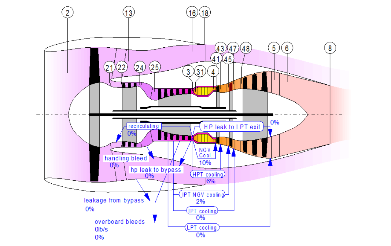
Figure 1. Stilistic cross section of a three-shaft turbofan with section numbers. Source: GasTurb.
The GasTurb cross section of a three-shaft turbofan is shown in Figure 1. We will use the station numbers in the figure to navigate the engine and the data from the simulation to understand modern airline engines and their typical data.
Intake
The intake of the nacelle (2) provides distortion-free air to the engine’s fan. At static takeoff mode, it provides around 1350kg/s (3000lb/s) of air with minimum pressure loss. To do this, the lips of the nacelle must allow the air being sucked into the intake from wide angles around the intake mouth without separation as the air curves around the intake lips.
At the same time, the nacelle provides around 450kg/s (1000lb/s) of air at cruise with maximum pressure recovery from the M0.85 free stream air. Now the lips must allow the air to spill over the sides because not all air hitting the intake area can be consumed, once again with minimum drag (no separation of flow).
The air entering the intake at cruise altitude of 35kft (10.7km) has a speed of M0.85, a density of 0.38kg/m3, a pressure of 238hPa and a temperature of -55°C. This compares with M0.0, 1.225kg/m3, 1013hPa and +15°C for a standard ISA sea level day.
The engine fan does not like air with an axial velocity of M0.85. Preferred speed is around M0.5 (otherwise the relative velocity to the rotating fan blades will be too high). The intake provides this by expanding the flow in a diffusion section before the fan, (2) in Figure 1.
Expansion of the air slows its speed, raises the pressure and the temperature. This changing of the air’s state by changing the duct dimensions will be done at several stages of the engine. Figure 2 shows the principle with a practical example in the engine on the right.
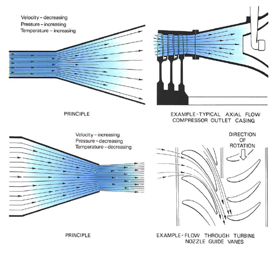
Figure 2. Use of divergent and convergent ducts to control air speed and pressure. Source: Rolls-Royce The Jet Engine.
The effect of the divergent intake (a diffuser section) is to raise the air pressure by about 1.5 times at cruise speed. With the intake diffuser section, we can adapt the axial velocity of the air to the desired ~M0.5. The final axial air speed will be a combination of the intakes influence and how much the engine is consuming air through the fan. In our example engine, we have a static takeoff air speed of M0.42, Top of Climb (final climb to initial cruise altitude) air speed of M0.51 and cruise M0.47.
Intake challenges
The making of a good nacelle is not easy. The intake must feed the engine at vastly different speeds without causing air distortion before the fan and cruise drag. The design of intake lips is an art.
Today the intake section is also made with perforated walls to dampen the supersonic shock waves that is created by the fan at full takeoff RPM (the see-saw buzz that one hears). And it shall all weigh an absolute minimum.
The fan
The purpose of the fan is to accelerate the air entering the engine’s intake to an overspeed (speed difference between aircraft and engine exhaust) appropriate for the thrust needs of the aircraft the engine is mounted on. As described in a previous Corner, the lower the overspeed is, the higher the propulsive efficiency will be for the engine.
At the same time, the thrust of the engine is overspeed times accelerated air mass. If we reduce the overspeed, we either reduce thrust or we must increase the accelerated air mass. The role of the fan is therefore to accelerate a large mass of air to a modest overspeed, sufficient to create the thrust the aircraft needs for takeoff and its climb to initial cruise altitude, the so-called Top-of-Climb thrust (ToC).
The thrust needed for cruise is lower than that needed for Top of Climb. For four engine airliners, the ToC thrust determines the flow aerodynamics through the engine. This is the aerodynamically most demanding point in the flight envelope. For airliner twins, the one engine inoperative thrust requirement after takeoff (the V2 case) can also be aerodynamically dimensioning for the engine.
Fan aerodynamic design
The fan for our example engine has a diameter of 118in and rotates with up to 2600rpm for max. takeoff thrust. This gives a blade speed at the tip of 413m/s, which at the sea level takeoff case shall be compared with a sound velocity of 340m/s. The blade tips therefore move with M1.2 at maximum RPM.
We also saw that the axial velocity of the air into the fan was M0.42. The two speeds vector combine when the air curves around the blade tip which results in an air speed relative to the blade of around M1.5. At the same time, the inner sections of the fan have blade velocities of around 145m/s, which corresponds to M0.4. The relative air velocity lies a bit higher but still in the subsonic range.
At different throttle settings and combinations of altitude and temperature, the fan will have different parts which are subsonic, transonic and supersonic (the speed of sound varies with temperature and to some extent on pressure).
The fan blade designer then needs to design a blade which can work efficiently at these different speeds. At the tip, it will have a profile that is efficient at supersonic speeds (thin profile with sharp edges), in between a transonic design and at the root a subsonic design.
During the engine’s different flight phases, the boundaries between these flow types will move up and down the blade. The design will therefore focus on having max efficiency for cruise RPM conditions, with acceptable function for max thrust and idle cases.
A modern fan has a conversion efficiency of the shaft hp (around 80,000 at takeoff thrust) to thermodynamic power (pressure, around 1.4-1.5 times, and increased air speed, average 280m/s at takeoff thrust) of around 90%.
Fan blade evolution
The historical fan blade had the same form as a compressor blade, Figure 3 and 4. The weight of the solid titanium blade stopped a wider cord design. The long and slender shape made it difficult to get the blades stable enough to avoid flutter (aero-elastic resonant deformation), therefore mid-blade clappers were needed. These caused efficiency losses due to shock waves that formed around the clappers.
As fan blades have a nacelle wall that stop tip streams, they don’t have to have a high aspect ratio to be efficient. As hollow titanium blades were developed, fewer wide-chord blades could be used. These are more robust and therefore could be made without clappers. Gradually the form was adapted to the different flow states over the blade.
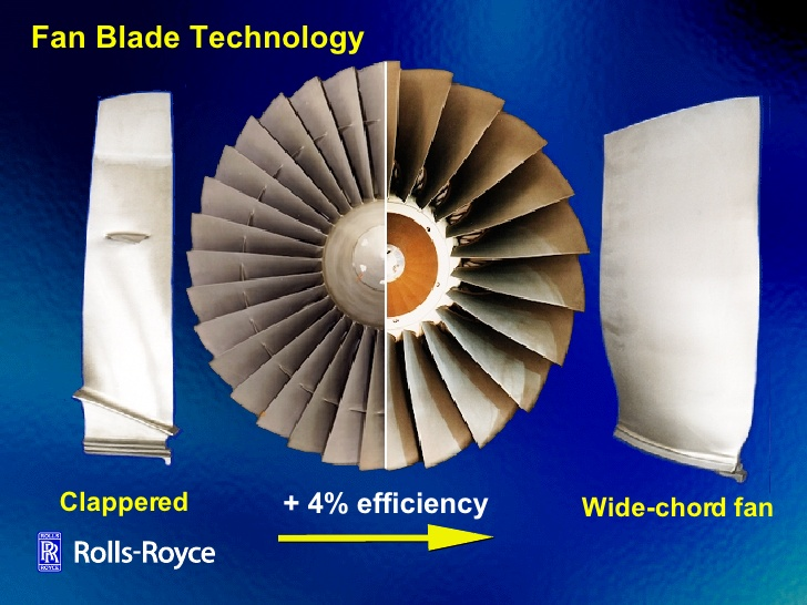
Figure 3. Evolution from narrow to wide chord fan blades for RB211. Source: Rolls-Royce.
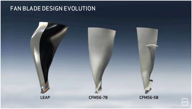
Figure 4. Fan blade generations for CFM’s single aisle airliner engines. Source: CFM.
The reduced number of blades also increases the flow area between the blades, thereby increasing the air mass throughput for the fan.
Fan blade construction
The historical fan blades were made of solid titanium. Hollow titanium blades as pioneered by Rolls-Royce use different honeycomb or web structures as internal stiffeners. GE pioneered the use of prepreg Carbon Fibre Reinforced Plastic (CFRP) construction for the GE90 blade, later also used for the GEnx.
CFM and Rolls-Royce has taken CFRP blades to the next level by using dry fiber tows that are placed in a blade form, Figure 5. The CFRP resin is then injected when the form is closed. This method allows a high volume of fan blades to be produced at acceptable cost.
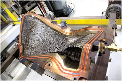
Figure 5. CFM’s CFRP LEAP blade form with the dry fiber 3D tow in place. Source: CFM.
Pratt & Whitney has developed an aluminum based wide cord fan for their GTF engine series. These blades are made as a hollow core with aluminum foam filler, with aluminum sheets bonded around the core. As for CFRP blades, a Titanium leading edge protects the blade from erosion and bird strike impacts.
Fan challenges
The fan section has several difficult challenges. First is to design a fan blade form which is efficient over a wide RPM and flight envelope. To achieve high efficiency the blade must be thin. To achieve the desired strength is must be thick. The result is highly sophisticated designs with air filled cores or CFRP designs with difficult to bond aluminium and titanium covers/leading edges.
The shear size of the fan blades makes them heavy. These heavy fan blades must be contained by the fan casing in the event of a blade off at full RPM. The fan casing therefore has a sturdy kevlar lined section outside the fan. The heavier the blade, the heavier the fan case. And modern turbofans are already to heavy. The quest for a lighter fan blade to turn the tide is the fan designer’s daily challenge.
Next Corner
In the next Corner, we will look at compression of the air in the engine core.
Great. I cant help but be more sold on LEAP ahead of PW Purepower. I’m not convinced by the idea of foamy aluminium layers. And they have reputedly had fan blade problems haven’t they?
“..The design [of the blades] will therefore focus on having max efficiency for cruise RPM conditions, with acceptable function for max thrust and idle cases.”
Sounds like a lot of statistics and big data would be involved to get the most out of it. Also sounds like another potential reason for variable pitch fanblades, aside from doing away with the thrust reverser. Also, isn’t the kevlar in the fan case being replaced with CF for the GE9X?
Also, is there a minimum number of blades on the fan needed to satisfy all these constraints? How few blades can an engine theoretically have before the benefits run out.
Love the article.
The Kevlar for fan containment case is replaced with Carbon Fiber from the GE90-115B and later, GEnX, LEAP… PWA choose the hard way of a metal composite Ti and Alu fan blade that is metal bonded together I assume. Even the RR all titainum alloy superplastic formed and diffusion bonded blades have had disbonds.
RR have previously said that they preferred the thinness of the fan blade roots that could be achieved and Titanium. It gives better aerodynamics feeding air into the core. I’ve read that they now think their CF process allows them to have thin CF blades too, so the full potential of the material can be exploited. GE’s CF blades are apparently quite chunky at the root.
So if they can make thin CF blades, and are not really limited in the shape they can make them, there should be plenty of room for improvements in performance.
Aluminium blades? I don’t see how that can be superior… might be cheaper and lighter than titanium, but surely CF is the way to go these days? Won’t they have to worry about fatigue life?
The reported issues are time to mfg, not a fault of materials.
I assume P&W has looked at it all before settling on the solution.
It all has to be integrated in with the over engine, and P&W works a lot differently with its Gear than the others so different considerations.
The initial GE90 carbon fiber fan blades had a life limit like helicopter rotor blades, don’t know if it still is there on newer designs.
It is harder with NDT methods to discover defects in carbon fiber/titanium blades than in regular Ti-6-4 blades.
You can see on the LEAP blade that the leading edge is bent so the normal component of the blade against the intake air reduces the effective aerodynamic speed the air hitting the blade l.e. sees hence reducing the strength of the air shock waves.
It could be interesting if Bjorn could get the blade out forces mechanical+aero during climb on the intakes explaining the SWA 737NG intake disintegration.
Love these articles Bjorn. Like everyone else, the foamy aluminium bit caught my eye.I was wondering how they were going to keep the weight comparable Has this technique been used for prop blades? Or is it the first time this has been tried? For those who haven’t been reading this up, there are a lot good reasons to go aluminium to do with dimensions, in particular you can make aluminium thinner without it becoming too fragile.
I have been wondering what the fundamental difference between a turboprop and a UDF is and why a turboprop can’t operate at high altitude, is it to do with the diffuser section? How does UDF cope with tip loss?
Hi Grubbie, this is the first time it’s used. It is enabled by the lower RPM in a geared fan causing less loads on the blade. The Airbus A400M turboprop operates at the heights as turbofan aircraft so no difference really. It’s more that short range regional aircraft use turboprop engines and these gains nothing by going much above FL250 for the short sectors they do.
what is the weight of a leap blade and how does this compare to older designs
Hi Dave, that is information that the OEMs keep closely guarded. I used the mechanical design feature of GasTurb to sketch a classical Titanium fan for a LEAP-1A style engine. It would have 29 blades, each weighing around 10kg each, i.e. 290kg total blade weight.
The LEAP-1A/C has 18 CFRP wide cord blades. You gain around 20% by going CFRP if your application is tensile strength limited which this is. I would guess around 12kg each but I could be off by a margin.
“The heavier the blade, the heavier the fan case.”
I’m not so sure, for the same application (787) a GEnx carbon fibre blade is heavier than a Trent 1000 hollow titanium wide chord fan blade. However the fan case is considerably lighter for the GEnx than the Trent 1000, perhaps more to do with material selection than the weight to satisfy the fan blade off containment certification criteria?
CFRP has favorable impact behavior (I would guess it shatters but I’m not sure, metal blades deform but stay in one piece), that is why the CFRP case for the GEnx-1 is lighter.
Thanks Bjorn, enjoying the articles.
My point was your claim in the article that weight of the fan case and fan blade have some kind of correlation, whilst comparing same material design this is true. If you are comparing metals to composites then the impact behaviour and certification requirements change this dynamic. I’ve seen metal fan blade off tests where a pack of C4 is strapped to the blade to prove fan blade containment, does anyone know if they do something similar for carbon fibre?
You can easily mess up a CFRP blade and a CFRP containment case depening how the fan blade brakes up at FBO impact. In worst case it breaks up into sharp objects that penetrate the CFRP containment case. The first GE90’s had CFRP blades with a heavy metal contianment case before they moved to CFRP on later models.
IMU GE proved that you never have to contain the full mass of one CFRP fan blade at point of impact with the fan case.
Worst case indicated as <50%.
That is a rather distinct reduction in requirement and thus in material needed.
It is the blade kinetic energy and the abradable material torque transfer that are important parameters, hence mass and rpm^2. The abradable material that the fan rubs against shall be quickly consumed at blade out events by the fan blades tips rubbing.
PWA has had some issues with its fan blades on the GP7200 and PW1500G and are not alone as RR had issues on Trent700 fan blades.
As Bjorn mentions, lower rpm/ strains enable other matrials, lighter blades and casings.
Handy when going into variable pitch blades, like RR is looking at.
http://brightcove.vo.llnwd.net/e1/pd/2468238088001/2468238088001_4285404472001_bannerUltraFan.jpg?pubId=2468238088001
Fiber oriented fans led to a near dead experience for RR in the early seventies (L1011 engine), one of the reasons they were conservative on crfp until everyone from that generation had retired 😉
Hi Bjorn,
As has been said in comments above, I don’t understand the use of aluminum by P&W for fan blades. Unless the argument is: It is not just the ultimate (or yield) strength of the material or its density that matters. It is the combination called specific strength, strength divided by density, what is usually denoted by Greek letters sigma/rho. Steel, titanium and aluminum alloy have specific strengths of 0.069, 0.122 and 0.150 MJ/kg. Thus it may be that P&W is onto something here. Aluminum alloy has the highest specific strength and so could yield lowest mass for the blades, with hollow core construction. Aluminum-Lithium is even better at 0.175 MJ/kg. Would you know if they are using Al-Li for fan blades?
Also for a fan tip speed of Mach 1.2 and axial Mach number of say 0.5, vectorial addition gives an overall Mach number of 1.3, not 1.5, which appears too high and is likely to cause too much buzz noise due to strong shock waves formed near the tips at such high Mach numbers.
The inlets are designed to minimize spillage losses at the most important cruise conditions. Sillage may be an issue under other operating conditions, such as TC.
Look forward to your next installment. Are you at liberty to publish the entire GasTurb output for whatever engine you have selected for discussion, e.g. RR Trent XWB? The reason is that component efficiencies such as the polytropic efficiencies of the compressor, fan and turbine are closely held secrets and it might help your readers to know what they are for a modern turbofan. So are Tt4 values at SLS, TO, TC and CR conditions. It also helps to know how SLS thrust and air flow rate (usually quoted by manufacturers) are related to the cruise, TO and TC values for this particular engine.
Hi Kant,
the PW blade uses Al-Li based alloys. I don’t have any specifics more than that but I think cost of production is also of importance. The choice of Al-Li should have been done after studies of all three types and PW say it-self that they were surprised how competitive the Al-Li based blade design was. The lower RPM of a geared design also lowers the tip speeds. They are just at speed of sound at sea level for the PW1000G so the vector sum should be just above the speed of sound. Any takeoff de-rate would probably place the fan in the transonic range.
I will discuss the important data including efficiencies as we go forward. Those will be typical values, as discussed I don’t have specific data for the Trent XWB, but I know where the state of the art is for the different parts. I can also adapt the simulation so that the known data fit. Modeling is a good way to understand what data fits with the data one has.
in a perfect world where you didn’t need to worry about things like the fan intake hitting the floor, what diameter fan would be the optimum size for an A320 engine. in other words how much bigger would fans need to become to reach optimum efficiency. Again not worrying about such niceties as such drag.
The point is Dave that you have to worry about drag and weight. As an engine manufacturer you only win the place on the aircraft if you improve the aircraft’s efficiency. The present engines optimize this with the available technology. Read this corner to understand more:
https://leehamnews.com/2015/09/18/bjorns-corner-engine-efficiency/
Björn,
Your courses are highly appreciated!
I’d like to question what you say about the fan:
“The purpose of the fan is to accelerate the air entering the engine’s intake to an overspeed”
To my knowledge, the fan (like the rest of the compressor) actually decellerates the air and increases the air pressure. The pressure rise across the fan is denominated “fan pressure ratio (FPR)”,
which is an optimisation parameter for fan efficiency. The higher-pressure air is then accellerated by the fan nozzle, to achieve the overspeed which is required to generate thrust. This is why they try to put variable area nozzles to low-FPR fans AFAIK.
https://ntrs.nasa.gov/archive/nasa/casi.ntrs.nasa.gov/20090035613.pdf
https://ntrs.nasa.gov/archive/nasa/casi.ntrs.nasa.gov/20110004165.pdf
Could you check with someone who actually knows in detail about jet engines, if I am mistaken?
Thanks a lot!
Steffen
I think your mistaken. I know very little about jet engines but last time I flew on a propeller aircraft I don’t remember seeing a nozzle yet we still flew.
I enjoyed reading the reports you referenced in your comment. I noticed that ignoring weight penalties and additional drag the propulsive efficiency is increasing as the pressure ratio goes down. This leads to the conclusion that for a ducted fan a pressure ratio of 1 would be more efficient than one greater than 1. In other words the fan is doing the acceleration of the air bypassing the core as it is in an open rotor system. The difference is the duct significantly reduces the fan tip losses without introducing significant pressure losses in the duct.
This does beg the question then why have a nozzle?
Dave,
The propeller works differently. The airfoils are chosen such that the propeller actually does accellerate the air – opposed to the fan which has a different airfoil shaping – AFAIK.
From a wider perspective, the propeller accellerates the flow without a change in pressure. In detail, shortly in front and aft of the blades, there is actually a change in pressure. The surrounding air acts as a duct.
From an efficiency point of view the nozzle only makes sense, if the fan works like I think it does. Point is that you can’t accellerate the flow with a propeller or an UDF when reaching high subsonic speeds. If the blades shall accellerate the flow at, say, M0.85 free stream speed, then you’ll have supersonic flow on the propeller/UDF which dumps efficiency.
Hence, do it differently: Decellerate the flow with the inlet to M0.5/M0.6 (as Björn correclty describes), add energy to the flow with the fan by increasing its pressure and then accellerate it by squeezing it through a nozzle. This way it works perfectly at high transonic speeds, and even supersonic (but you’d need a different nozzle then, of course).
Dear all, why in a turbofan engine, last thing in LPT is a rotor?? Nozzle in the last can further increase the exhaust velocity wch can increase the thrust. Can anybody give a logical answer.
What is the range of aoa that the fan handles? The treatise explains that the inlet duct very effectively constrains the range of mach numbers that the fan sees. Still, from maximum rpm zero speed at takeoff to high mach/lower rpm cruise, optimizing aoa for a fixed pitch fan must be significant.