Leeham News and Analysis
There's more to real news than a news release.

Bjorn’s Corner: Engine rubbing
 09 October 2015, ©. Leeham Co: Last week an Airbus A320neo prototype with Pratt & Whitney’s (PW) GTF had a problem while testing hot and high conditions at Al-Ain airport in Abu Dhabi. The engine suffered a rubbing problem and PW and Airbus decided to replace the engine before returning the A320neo to Toulouse.
I had the opportunity to discuss what happened with PW people at ISTAT this week and decided it makes for a good follow up to our two other engine Corners to write about what happened and how serious it was.
The problem was compressor blades rubbing against the compressors stator wall. PW knew that this engine individual could have that problem. They saw when assembling the engine it was a bit tight in the compressor area. PW said they told Airbus there was a risk with this particular unit, and sure enough, there was rubbing to be seen when they boroscope checked the engine after the test.
Here what it was all about and what to do about it.
Turbofans and how they function
As I have written in previous Corners, turbofan engines are air pumps. The dominant pumping is done by the fan (90%) with about 10% of thrust coming from the gases coming out of the core. The core gives shaft power to drive the fan. It does this by compressing air and then mixes it with fuel in the combustor and burns it to get hot gasses with high pressure. These then generate shaft hp in the turbines which drives the fan and compressors via shafts.
Both the compressors and turbines are made of a rotating part (compressor/turbine rotor with blades) and a fixed part (compressor/turbine stator with blades), see Figure 1. The compressor gains pressure for each rotor/stator combination. The turbine does the reverse; it uses the high pressure gases from the combustor to extract shaft hp and the pressure and temperature falls for each stage.
Tip leaks
To have the compressor’s pressure gain using the minimum of shaft hp and the turbine pressure fall generating the maximum of shaft hp, it is important these stages having no leaks of air in the direction of lower pressure. The main leak opportunities are at blade tips, Figure 1.
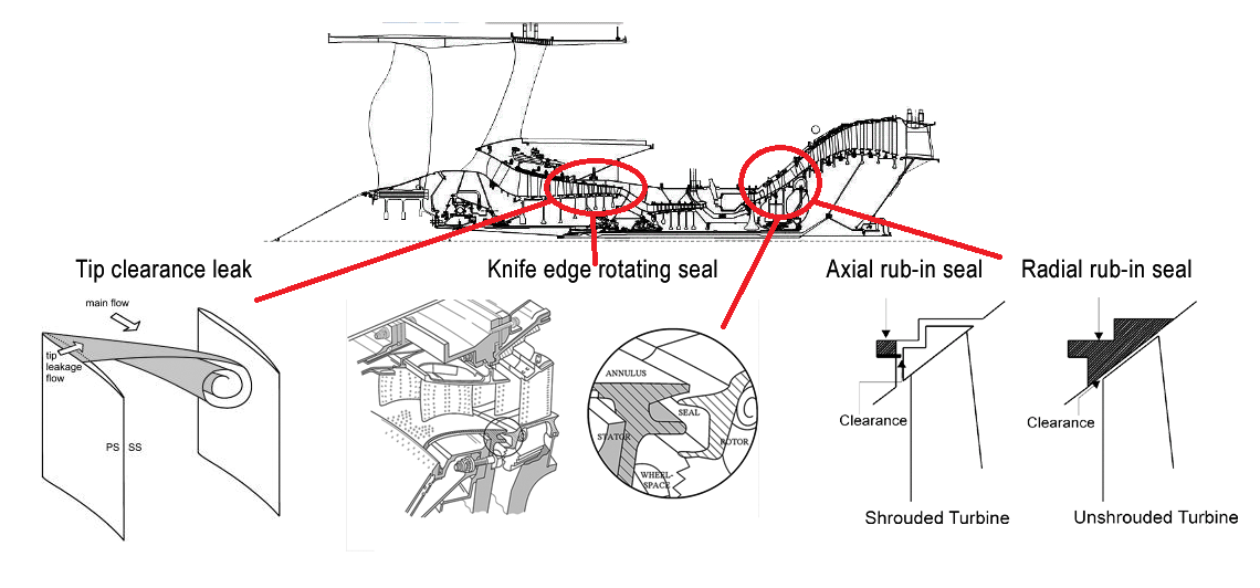
Figure 1. Leaks and seals in a turbofan’s compressors and turbines. Source: Google images and Leeham Co. Click image to enlarge.
Air would leak past the tip and into the stream on the blade’s back side and therefore back to the previous stage in the compressor, thus lowering the stage’s compression ratio. And it would leak past the turbine blade to the next stage without pushing the turbine blade to generate shaft hp.
Therefore, the tip clearances of compressor and turbines are made as small as ever possible. It is a play with tolerances and sometimes one gets the tolerance too tight in production and there is rubbing, blade-tip to stator shroud.
Rotating seals
The other area where air can slink through is at the blade roots. The root area is sliding past the inner part of the stator on both sides of the blade. The middle figure in Figure 1 shows the forward seal of a turbine stage. To seal this area, rotating seals are used, here shown as knife edge seals. Other solutions use different brush structures, all trying to stop air slinking past the seal.
Rub or no rub
There are different methods to get to minimal leaks over the blade tips. Turbine stages have high stage pressure drops and calls for tight solutions in an area with high thermal movements and stresses. For turbines, Rolls-Royce has been using blades with tip shrouds, Figure 1. This pushes the problem from tip leaks to a rotating seal problem, which is easier to handle when the blades grow with temperature and centrifugal forces. The drawback are heavy blades, which require a beefier disc to compensate, the engine gets heavier.
The alternative are blades which are allowed to create their own tip clearances by deliberate rubbing. These blades have tips equipped with hard metal implants that scratch their needed clearance from a stator shroud made with a forgiving material. This is often complemented with a stator shroud which can contract and expand through an active tip clearance control system. This way of getting the high pressure turbines to have minimal leaks is used by PW, GE and now also Rolls Royce for the Trent XWB 97k’s high pressure turbine.
For the low pressure turbines (LPT), normal tips with close clearances are used, aided by control of the tip clearances by controlling the stator thermal expansion through throttled cooling tubes passing over its surface. The cooling uses air from an early compressor stage. Once again Rolls Royce uses shrouded blades instead of stator cooling for the LPT.
For the compressors, the stage pressure gain is smaller than for a turbine stage (1-2 versus a fall of up to 5 for a high pressure turbine stage) and it is not worth the trouble with shrouded blades, rubbing tips or throttled cooling of the long compressor stators. Here the technology is to run close tip clearances once operating temperature has been reached (up to 700°C at the last stages).
The manufacturers therefore produce compressors with the closest gaps possible between the blade tips and the stator shrouds. Sometimes it gets to close as in the PW Al-Ain case. PW recognised it was a close case when assembling the engine and told Airbus to check it during the tests.
Clearances don’t scale with size
Compressors need to shrink the dimensions of later stages as the air gets more compressed and takes less space. Subsequently, the blades get smaller. For small engines, it is not possible to shrink the tip clearances in proportion. Large tip leaks are the result. This makes small axial compressors hard to make efficient, especially for the last stages.
Therefore small engines (turbonfan as well as turboshaft) use radial compressors for the last compressor stages, Fig 2.
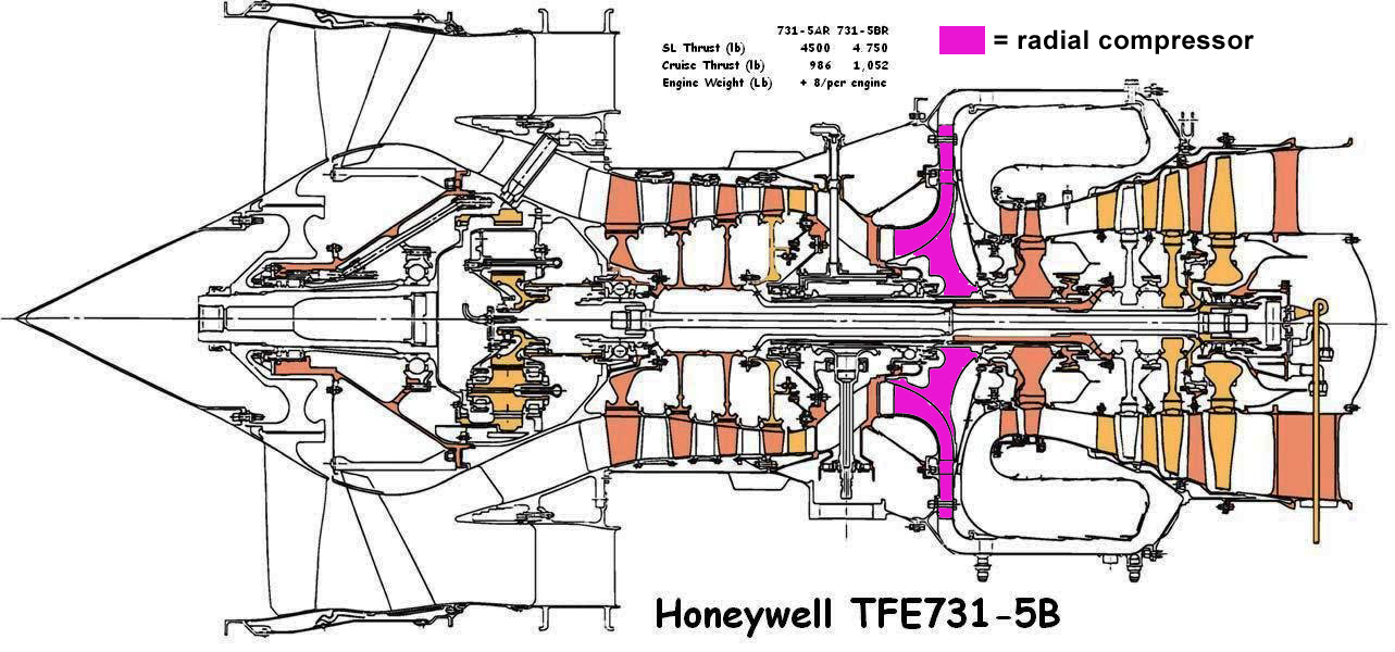
Figure 2. Honeywell TFE731 Business jet turbofan. Source: Honeywell.
A radial compressor has a larger stage pressure gain and therefore replaces several of the last axial stages. It also has larger dimensions and is therefore easier to manufacture for acceptable efficiency.
The large radius (it decides the core’s diameter for this engine) is why it is not used on earlier stages or when the core’s dimensions makes axial stages effective.
Summary
To have an engine rub its blade tips against the outside walls is not good unless it is designed to do it (turbine example). But it is in most cases a matter of getting manufacturing tolerances right and engine testing is where to find the last fractions of these tolerances. The Al-Ain problem was therefore with high probability a manufacturing problem.
This is different to PW’s last problem on the Bombardier CSeries. There the rear bearing compartment’s rotating seals did not make oil stay put in the compartment. You use a deliberate compressed air leak over the rotating seal, pushing air into the compartment, to stop oil from travelling past the seal. PW needed a fix to get that right.
For the rubbing, the fix should be that they open up their manufacturing tolerances a tad.
Thanks as always Bjorn.
Because tip clearances don’t scale with size, what effect does this have across the range of large commercial turbofans? Any estimate of how much tip-leakage efficiency loss for a 50k lb-T engine versus a 100k engine?
I would not know that and as Herb said, from an engine design point of view it is covered in the compressor transfer efficiency number. These range from 0.85 to 0.95 depending on design time period (3d flow design or not), compressor size (radius), stage loading/PR and if running at optimal mass flow etc.
Thank you very much Bjorn !
What is the current limit of radial (centrifugal ? ) compressor?
Bonne journée
Centrifugal compressors are typically limited in the stress at the outer diameter (which limits the shaft speed). I am not up to date on centrifugals so cannot give a definite answer on the max pressure ratio, but up towards 10:1 should be possible with modern materials.
Downside is difficulty in building multi-stage variants (unless coupled with an axial machine) and increasing the core radius, pushing the fan channel out (and providing a 90deg turn from compressor outlet to combustion chamber).
Hi Björn,
great read as always, although I would like to correct a mistake in your article.
Al-Ain (and its airport) is not in Abu Dhabi, but rather, like Abu Dhabi, one of the seven Emirates that form the UAE.
Keep up the informative work!
Great read, and as a resident of Al Ain, it answers the question of why A320 NEO had a tent around the engine while it was sat on the tarmac last week.
For clarification Al Ain is indeed part of Abu Dhabi. Abu Dhabi is a city, but is also an Emirate in its own right (somewhat similar to New York city and New York State).
Similar issue to the doomed F-35 from a few years back…
the F-35’s rub problem, while fundamentally similar (rub in tip clearances were too tight) they were exacerbated by high G forces and an insufficiently strong fuselage structure imposing bending loads on the engine that were not anticipated in the design.
in trying to get every last ounce of thrust out of the F135 to cope with the fat pig that is the F-35’s weight growth, P&W pushed a bit too hard on the tip clearances. remember the F135 is basically a 15% throttle pushed F119 (and we know from Bjorn’s previous post what throttle pushing does for maintenance costs)
Bjorn, Very informative as always. The main effect of increased tip clearance in the compressor is to lower compressor efficiency, requiring more power from the turbine resulting in loss of thrust. Major manufacturers have had different design philosophies on turbine tip clearance, Pratt and GE have always used unshrouded first stage blades but RR used shrouded blades, believing this gave better control of tip leakage. But tip shrouds are undesirable from stress conditions, and with increasing tip speeds RR have gone to unshrouded blades on the Trent XWB. Note that virtually all last stage blades on big engines have tip shrouds to minimize vibration of the very long high aspect ratio blades. It is of historical interest that the CFM 56-2 used to re-engine the DC8 had a tip shrouded fan, I think this was unique. Centrifugal compressors are temperature limited by using titanium and the Max OPR with final centrifugal stage seems to be about 25. Centrifugals are certainly capable of PR of 8 ( PWC 200, RR 250) , but when following several axial stages the PR will be much lower because of the higher inlet temperature.
Herb,
great to have you chipping in here. There is a lot of spread knowledge on the airframe, less so on engines, work to do 🙂 .
The CFM-56-2 is known as the grand-dad of the CFM 56 family and was first 10 tonne high bypass engine.
Interesting that its first flight in 1979 was on a B707, not DC-8, but Boeing decided not to re-engine this model, rather pushing its new twin, the 757.
A question:
Energy transfer in fluids is via both pressure rise and velocity increase. Could I improve on tip losses if the rotor stage does speed increase while the stator stage does pressure recovery?
( downside probably more stages required.)
IMU radial commpressors only increase flow speed while pressure recovery is done in the outer manifold?
Final solution will probably go towards more active tip clearance control, right?
It’s curious that this story (I first saw it on AvWeek) has almost gone completely unnoticed and un-commented upon, especially for all the GTFans out there (yeah, I’ve named the GTF fanboys).
While the CFM (yes, you can call me a CFM fan) has been humming right along, with no apparent issues. Meanwhile, PW has their hands full with the F-35 BBQ they had, the C-series engine problem and not this.
the GTF issues have been a bit disappointing, with both the C-Series and the NEO having significant stand downs due to engine design flaws seemingly much later in the development process than you would hope to find such basic issues.
This particular issue though seems to be the kind of thing you would expect in a pre-production engine where they haven’t quite got their manufacturing processes dialed in and it came off the line built a bit too tight, PW knew about it and asked Airbus to keep an eye on it and by the time it became an issue, they had a hot spare in inventory to replace it.
P&W has proven its a second tier player, they also gave away tech to China a while back.
They may get up to speed but their engine division has not had a good track record for some time.
I believe in the GTF but P&W has a lot of work to do to convince me they can step up.
That technology was connected to small engines for a military attack helicopter, and the culprit was P&W Canada. The premeditation and lies told afterwards are akin to those of Volkswagen today. It was done in the early 2000s , but be interesting where those involved are today ?
Allan Bellmare, now CEO of Bombardier was a senior executive at P&W Canada from 1996 and CEO in 2002.
It seems there’s confusion as to whether the rubs were at blade tip shroud segment, or at blade long edge to stator. The early description credited to PW seems to align with the latter.
This is important as tip rubs are a normal sort of event with hard landings but wipes of blade to stator are more associated with design issues, the most basic being a lack of clearance for the available stiffness.