Leeham News and Analysis
There's more to real news than a news release.

 Leeham News and Analysis
- GE testing of giant GE9X engine aims for maturity at entry into service June 30, 2025
- Bjorn’s Corner: Air Transport’s route to 2050. Part 28. June 27, 2025
- Parent agency, FAA often at odds as politics outweighs safety June 26, 2025
- Electric Flight and the Ugly Duckling June 25, 2025
- Engine makers tout “Plan A” but have “Plan B” backups in R&D June 23, 2025
Bjorn’s Corner: Sustainable Air Transport. Part 12. Hydrogen storage.

By Bjorn Fehrm
March 25, 2022, ©. Leeham News: Last week, we looked at the energy density by mass and volume for hydrogen and regular Jet fuel (Kerosene), Figure 1.
With this information, we now look at how these fuels can be stored in an aircraft.
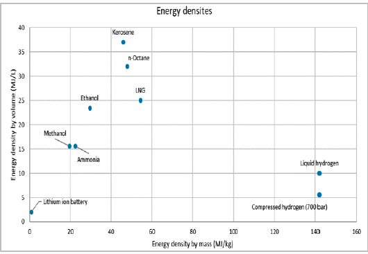
Figure 1. The Volume and Mass densities of fuels. Source: Boeing.
Storage of Jet fuel/SAF in an aircraft
The storage of today’s Jet fuel and the “drop-in” SAF (Sustainable Aviation Fuel, either biomass or Synfuel based, see Part 11) is almost “for free” in today’s aircraft, Figure 2.

Figure 2. The fuel tank system in an Airbus A320. Source Airbus.
The fuel is stored in the wing’s winbox, which forms a natural tank with its forward and rear spars and wingcovers top and bottom that closes the box. The ribs in the wingboxes keep the wingcovers and spars in place but also function as compartment- and end walls for the fuel.
The center wingbox is not used for fuel unless needed, as it stores fuel away from the aerodynamic lift of the wings and, therefore, increases the wing root bending moments.
In Figure 2, extra center tanks in the rear cargo hold are shown. These are used for extra long-range aircraft variants (more common for the A321 than A320) and are proper tanks with their own structure to hold the fuel.
The additional mass spent in the aircraft for its fuel is the sealing compound for the wingbox tanks, fuel pumps, tubes and valves, and any extra equipment such as the oxygen depletion system to make the tank air above the fuel non-explosive.
The typical mass for such a fuel system for a single-aisle airliner is around 500kg.
Hydrogen storage tanks
The storage of hydrogen is trickier than Jet fuel. You can’t use a compartment formed by the aircraft structure like for Jet fuel.
For hydrogen, there are two choices, gaseous storage or liquid storage.
Gaseous hydrogen storage
As gas storage of hydrogen at normal pressure and temperature would need 3000 times the space of Jet fuel for the same energy content. Thus, a gas alternative stores the hydrogen under high pressure to compress the volume.
The aviation sector has adopted the car and truck industry’s 700bar/70MPa/10,000PSI compressed hydrogen storage method. The gas tanks are made of a leakproof polymer liner and a carbon fiber shell, figure 3.
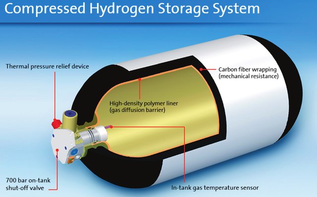
Figure 3. The 700 bar tank from a General Motors fuel cell car. Source: GM.
The advantage of the gaseous storage of hydrogen is the availability of hydrogen in this form and you can store it for a long time without leakage of hydrogen.
The disadvantage is the volume of the tanks (they occupy six times the volume of jet fuel for the same energy) and the very high mass of the tanks. Typical for these tanks are a Mass Fraction (defined as hydrogen mass divided by tank + hydrogen mass) of 6%.
If we want to equip a DH8-300 with energy equivalent to its 4,600kg fuel capacity, we need storage for 1,600kg H2 (Jet fuel divided by the 2.87 times higher energy content of H2, Figure 1).
If we store this in a 700 bar tank, the tank with hydrogen weighs 26,700kg. This mass is impossible to handle, and a volume six times the jet fuel is problematic. It’s why gaseous hydrogen is used for demonstrators (due to the convenience) and extreme short-haul projects (island hopping etc.).
Liquid Hydrogen Storage
The alternative is liquid hydrogen storage. Now the hydrogen is stored at its liquid phase temperature of -253°C in tanks with a pressure of around 1.2 bars, Figure 4.

Figure 4. Liquid Hydrogen tank example from Airbus. Source: Airbus.
The advantage of this storage method is an acceptable mass. To store the energy of our 4,600kg of Jet fuel, we need 1,600kg of LH2, and the tank with LH2 would weigh 4,600kg, the same as our Jet fuel. We have then assumed a Mass Fraction of 35%, which is the projected fraction for tanks of this size.
The drawback is an LH2 volume that is four times larger than the Jet fuel volume, and it must be stored in a minimum external surface tank like in Figure 4 to minimize heat influx through the tank walls (these use vacum flask and polyurethane insulation to minimize heat influx to the LH2). It means more aircraft mass as the LH2 can’t be stored “for free” in the wings like Jet fuel.
Another drawback is LH2 boil-off as the tank content can’t be 100% isolated from the surrounding atmosphere. This makes LH2 tanks a short-term storage method.
Conclusion
The debate about gaseous or liquid storage of hydrogen in airliners is a pseudo-debate. The only viable storage form for projects outside extreme short-haul is liquid hydrogen. Gaseous storage’s weight and volume consequences are unacceptable for any airliner use, regional or mainline.
We explore the aircraft-level consequences of LH2 as fuel for airliners in coming articles.
Solid state hydrogen storage materials – light metal hydrides, intermetallic hydrides can also perform as structural components of a system. When hydrogen is stored in its solid state through metal hydrides, it does not need to be compressed or liquefied. A cubic metre of hydrides can contain far more hydrogen than a cubic metre of LH2. The balance of plant is also less.
Conceptual designs I have seen consist of a “cassette” inserted into the vehicle at the start of its work cycle but when the chemistry is improved they would for part of the structure.
Isn’t weight also a problem for hydride storage? The mass fraction for metal hydride storage as far as I know is even lower than for the storage methods mentioned by Bjorn.
Yes.
A design can be envisaged which employs the hydride as a structural component. Further, aerogels are also being tested for both structural supports in hydride systems and themselves as absorbants of hydrogen.
Aerogels have densities little greater than air. Imagine a wing the internal volume of which is stiffened with a hydrogen saturated aerogel.
I don’t think the LiTi alloys are very dense and they do satire hydrogen at twice the density of cryogenic hydrogen between the metal lattice. My guess is LiTi alloys are too expensive, they require reheating and are prone to oxygen contamination. They do work. The German navy has been using them successfully for over 10 years on their type 212 u-boats.
There are many interesting thermal management synergies open for exploitation. The cryogenic fuel can be used to cool engine parts, as opposed to, e.g., using compressor bleed air for cooling of turbine blades and other parts. The boil-off can be recycled and fed to a fuel-cell APU, which generates heat that can be used for de-icing and so forth. In a way, the cryogenic temperature of the hydrogen fuel can effectively be thought of as an additional source of stored energy available to the aircraft if properly taken advantage of.
Absolutely, there are even more imaginative methods in the works from our engine OEMs.
Indeed, the liquefaction of H2 to LH2 costs energy but this asset is with you in the air and it’s about using it efficiently. As both a fuel cell and a gas turbine solution is all about heat management, this asset must be utilized and used cleverly. I’ll cover it in the series.
Reaction Engines would like to feed its high performance heat exchangers with it and cool different parts of the jet engine that benefits from cooling either in performance or using cheaper less heat tolerant materials (that often are cheaper to repair). For safety they might use a helium cycle in between as in their air breathing rocket engine (they used helium in their thermodynamic cycle to drive the LH2 turbopumps and LH2 to cool and liquify helium after it absorbs the inlet air heat).
Hi Bjorn,
Thanks for illuminating series of articles, especially on limitations of electric propulsion for aircraft.
A minor quibble.
The plot you show from Boeing is a bit misleading. I believe it shows the higher heating value, which is obtained when water vapor in the combustion products condenses releasing its latent heat value. As such, it is not appropriate for aircraft applications, since water is in the form of water vapor in the exhaust and lower heating values must be used. For example, H2 has a higher heating value of 142 MJ/kg, whereas its lower heating value is 121 MJ/kg. The Boeing plot shows higher heating value of 142 MJ/kg.
My back of the envelope calculations show 34.6 MJ/L (43.2 MJ/kg) for Jet fuel , 8.57 MJ/L (121 MJ/kg) for LH2 and 6.85 MJ/L (121 MJ/kg) for 700 bar GH2 at 25 C. Thus the volumetric energy density ratios are 0.248 for LH2 and 0.198 for GH2 at 700 bar.
Can you please verify? Thanks.
Thanks, Kant, appreciate it. I will look into it.
Hi Kant. Sorry for the late answer. I used the diagram to show the differences. I use data from a table made by LTH and ExxonMobil, where the values are at 15°C but very close to your values. From where did you get your values?
Also the failure mode of a 700 bar GH2 tank is a catastrophic explosion, whereas that of a LH2 tank is not that severe, so that safety issues also prohibit its use in aircraft propulsion. But impossibly huge mass as Bjorn described trumps this anyway.
I doubt it’s an issue. Any impact forceful enough to compromise a 700 Bar 9600psi tank would mean the occupants of the vehicle are deceased already. The high pressure probably greatly strengthens and stabilises the tank and we may find greater safety. It would be interesting to see Toyota’s crash testing. There is likely a flow limiter in the neck of the tank.
‘The high pressure probably greatly strengthens and stabilises the tank ‘
So its H2 content never used to ‘maintain the strength’ At many flights it will only 1/3 of the energy at end of flight- during landing phase too. Whats the reduced pressure then ?
It doesnt seem rational anyway that the pressure of the contents strengthen the container. ( unless they are low pressure flexible walls) The stresses in the wall , yes, but they are the source of the strength to begin with and any ‘unbalance’ in stress doesnt seem likely as the pressure is equal at all points
It is quite common in the rocket business to have the internal pressure stiffen the shell, called Stress stiffening from my Ansys days. It need some clever engineering to replace the fuselage over a section from the cabin aft pressure bulkhead until the tapered tail structure starts. You need small service channels on the outside for power and control wires and maybe others depending on where the fuel cell APU is located.
Thats confusing ‘stressed skin’ monocoque thin shell design, as used in aeroplane fuselages . The skin takes loads not just the strengthening members. Not using the ‘pressure to strengthen’ but using the skin as structure
‘Second, curved shell structures, as in a cylindrical rocket barrel, are one of the most efficient forms of construction found in nature, e.g. eggs, sea-shells, nut-shells etc.. In thin-walled curved structures the external loads are reacted internally by a combination of membrane stresses (uniform stretching or compression through the thickness) and bending stresses (linear variation of stresses through the thickness with tension on one side, compression on the other side, zero stress somewhere in the interior of the thickness known as the neutral axis). As a rule of thumb, membrane stresses are more efficient than bending stresses, as all of the material through the thickness is contributing to reacting the external load (no neutral axis) and the stress state is uniform (no stress concentrations).”
Another reason why passenger planes will stick with thin shell curved structures not these claimed ‘futuristic’ shapes.
https://aerospaceengineeringblog.com/rocket-science-101-lightweight-rocket-shells/
Atlas and Centaur are pressure stabilised structures: these rockets would collapse under their own weight on the launch pad unless pressurised. Falcon 9 is flight pressurised by propellant gas. It can support its own weight on the launch pad (it’s a fly back booster after all) but needs pressure stabilisation during flight. I imagine an aircraft hydrogen tank would also be stronger under pressure. Any breach of the tank if detected should probably initiate depressurisation.
Those rocket stages that you mention , Centaur type, are balloon type with positive pressure required to ‘keep their shape’
I mentioned this earlier but was thinking of the baseball stadium , which did fail under snow load .
Keeping one way rocket stages under pressure is a long way from commercial aviation and would never be allowed.
I understand the latest Atlas EELV rockets don’t use balloon shape pressurisation
@Dukeofurl, back to my point to the OP the extremely high pressure in a gaseous storage tank is unlikely to be a danger and the high pressure in an impact related crush. I suppose what one would want is that if someone fires a 50 caliber AP round into the tank the tank is at worse penetrated but does not rupture or “rip”. One would want a flow limiting fuse inside the neck of the bottle to seal of the tank prevent it turning into a rocket. A pressure relief valve to prevent over pressure and some kind of thermal fuse to release pressure at temperatures likely to compromise the vessel. If an ATR72 or DASH 8 with these bottles had a survivable crash the bottles must remain uncompromised. I can’t see an issue with this.
Having read a number of your great articles on hydrogen fuel for airliners my sense is that is perhaps a step too far for practical usage and seems like it will always use up a lot of the fuselage volume. Also you must use hydrogen from electrolysis using near zero carbon electricity for this to have it’s environmental benefit.
LNG (methane) has considerably higher heat content per carbon atom than kerosene (thus less CO2 per unit of energy) and has (per your chart) 2.5 times more energy per volume unit than H2 allowing it to be stored in cylindrical tank(s) below the cabin floor. LNG also has about 15% more energy per unit of mass (per your chart) than kerosene which would partly offset the mass of the tank(s).
It is obviously not a near zero CO2 solution like using H2 but it does offer lower CO2 than kerosene. How does it “pencil out” in terms of CO2 reduction per dollar (or Euro) compared to the more difficult task of using hydrogen?
-I suspect bifuel SAF and/or hydrogen engines will make an appearance. Both diesel and spark engines work on 100% hydrogen fuel. Modified Diesel engines work well on a blend of hydrogen and liquid fuel. They will idle on 95% hydrogen and run on 70% hydrogen under full load and switch to 100% liquid fuel instantly. Even small additions of hydrogen significantly improve efficiency (easily 5%-7%) and reduce emissions.
-Jet engines could also be bifuel hydrogen SAF. Compromises would be that the combustion chambers couldn’t be shortened as much and precooling and intercooling would not be available when out of hydrogen.
-However bifuel engines would allow wings to be still used for storage free of CoG issues, allow flights out of airports lacking cryogenic facilities and have greater range. Much of the SAF would be held back except when needed as a divert, go around, hold or headwind reserve.
The bi-fuel engines might be a way to avoid burning JET-A over a certain country that prohibits it or more likely heavy tax it. Then as soon you leave its border or come out on international waters you switch to JET-A. It can be a step on the way and much more easy to implement. The easiest way I think is high pressure gas tanks similar to drop tanks under the wing as plenty of space is available on twin engine aircrafts. It also makes H2 easier to manage at airports especially if hooked up to natural gas pipeline systems boosted with H2 that you can filter out.
-I had thought that PEM fuel cells had some miracle efficiency of around 60% but checking finds the real world efficiency more around 40-45%. The Toyota Mirai does achieve better economy than its hybrid synergy drive equivalent suggesting suggesting superior efficiency but I think its superior part load efficiency, a area more important in cars.
-Toyota is testing a hydrogen spark ignition internal combustion engine Yaris car running of gaseous hydrogen. Liebherr and Bosch have engines on the test bench.
-Fuel cells may not be needed.
-These Otto engines use stratified charges or prechambers (Liebherr) where a prechamber is ignited which than shoots a jet into an extremely low lambda ‘lean’ air fuel mixture to achieve reliable ignition This mostly eliminates the NOX issues. I can imagine using a different fuel in the different chambers.
-The trucking, mining, earth moving and diesel generator industry is looking at how it can decarbonise. One thing is bifuel diesel/hydrogen engines. Sometimes referred to as ‘hydrogen enabled’
-Why shouldn’t this be applied to aircraft diesels (and gas turbines)
-Simply adding a small amount of hydrogen via thedisel intake valves, say 5% by energy actually greatly increases the efficiency of a diesel and typically reduces NOX and particulates by 60% to 80% and efficiency around 7% or more. The improvement is so significant that its worth having an electrolyser running of the engine alternator.
-The other way is to inject the hydrogen at top dead centre. This replaces most of the diesel (70% at full load, 95% at part load).
-There are other ways. DME (Dimethyl Ether a non toxic butane like substance) used as an ignition mixture for RCCI engines in formula 1 and also used in the BMW/Daimler Benz experimental HCCI engines of 1930s and 1940s could be used. DB tested to 44,000ft. They could achieve thermal efficiencies of 55%. DME can replace diesel almost drop in and is easy to synthesise.
-As I see it a bifuel aero diesel (or gas turbine) in an aircraft would be able to conduct flights under 300nmi on 80% hydrogen and 20% SAF. The reserves (hold, go around divert) can be covered by the SAF portion and will seldom be used except on longer flights.
–
–
It appears that the Mass Fraction analysis for gaseous H2 has not considered the effect of the square-cube law. The mass of the tank would be expected to increase with the square of the linear dimension, but the mass of hydrogen increases with the cube of the linear dimension. So the Mass Fraction will increase significantly as tank capacity increases. The folks at Universal Hydrogen (hydrogen.aero) must have done the math, and figured that this concept is going to work.
There is no such effect.
Increasing the dimension of the tank you must increase also the thickness (and therefore the mass of the tank grows with the cube of the linear dimension)
You have a small gain only considering the inlet/outlet piping.