Leeham News and Analysis
There's more to real news than a news release.


Bjorn’s Corner: Pitch stability, Part 5

By Bjorn Fehrm
Jan. 11, 2019, ©. Leeham News: The week before Christmas we discussed the pitch stability of an airliner. We covered how a horizontal stabilizer made the aircraft stable in pitch, and why transonic airliners used a trimmable horizontal stabilizer rather than trimming with the elevator.
Now we look at some different flight situations with different trim needs before we move into the more troublesome parts of a pitch moment curve.
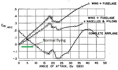
Figure 1. The pitch moment coefficient curve of an early DC-9 candidate. Source: Stanford University.
Bjorn’s Corner: Pitch stability, Part 4
December 14, 2018, ©.Leeham News: Last week we introduced a horizontal stabilizer to make our DC-9 like aircraft stable in pitch. We got a pitch moment curve which was forcing the nose down of the aircraft if there was an increase in Angle of Attack (AoA) of the aircraft. Should the angle of attack decrease from a trimmed position, the aircraft would put the nose up to correct the disturbance. The aircraft is stable in pitch.
Now we take a closer look at how such a horizontal stabilizer is made and why.
Figure 1. The pitch moment coefficient curve of an earlyDC-9 candidate. Source: Stanford University.
Read more
Bjorn’s Corner: Pitch stability, Part 3
By Bjorn Fehrm
December 7, 2018, ©. Leeham News: Last week we looked at the pitch stability of an aircraft wing with fuselage. We could see the combination was unstable. Now we add a rear wing called a horizontal stabilizer to get the whole aircraft stable in pitch.
We use the DC9 as our example of a pitch stable airliner (Figure 1) as it has some interesting pitch stability problems outside the normal flying envelope. This we will discuss in coming Corners.
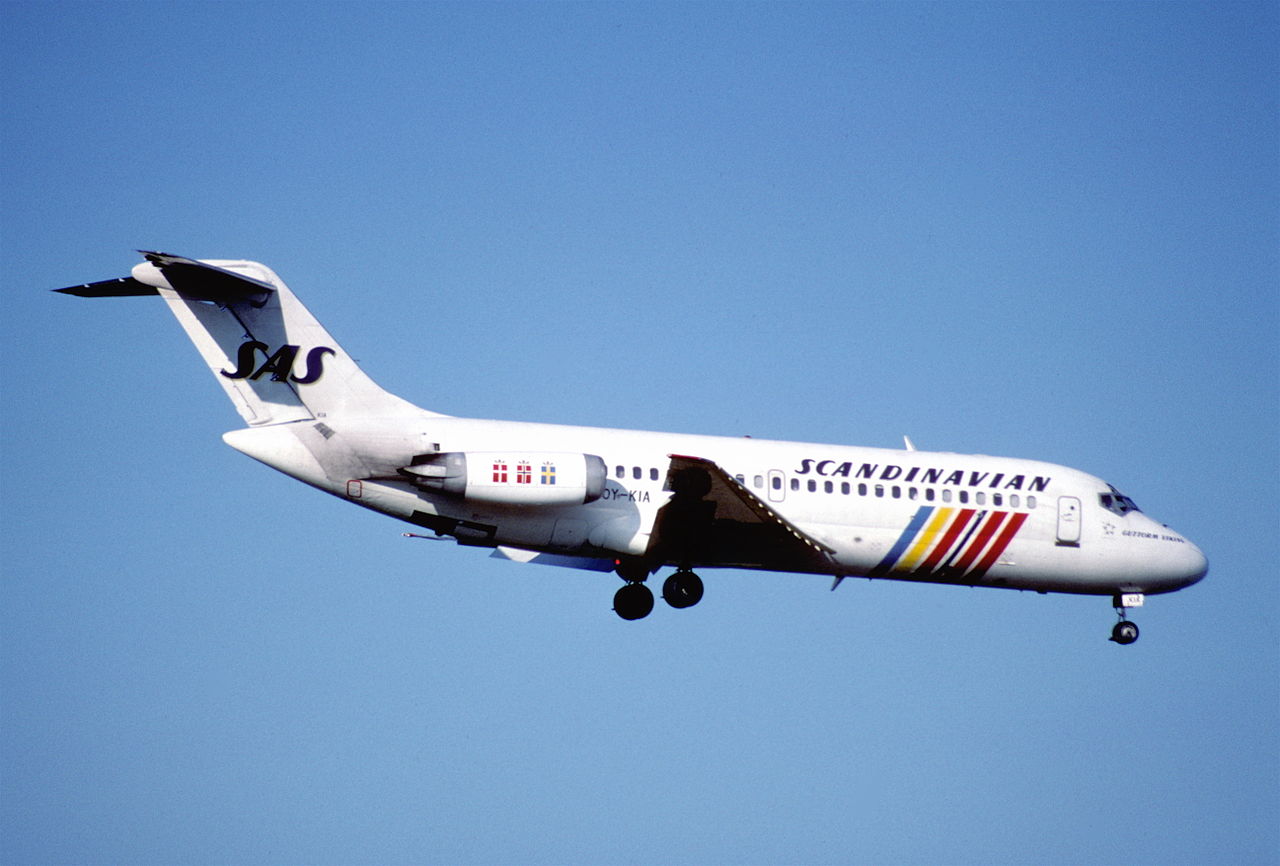
Figure 1. The DC-9, the airliner we use to study pitch stability. Source: Wikipedia.
Bjorn’s Corner: Pitch stability, Part 2
By Bjorn Fehrm
November 30, 2018, ©. Leeham News: Last week we started a series on pitch stability of aircraft. It has actuality as the reason Boeing introduced the now well-known MCAS (Maneuver Characteristic Augmentation System) was to improve the pitch stability of the 737 MAX.
We discussed the pitch stability of the basic wing last week. This week we add the fuselage and see what happens.
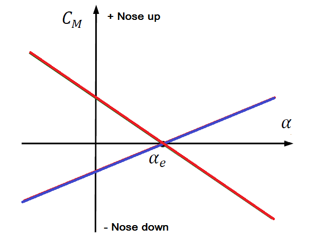
Figure 1. The pitch stability of two different wings, Violet (Classic profile) and Red (Supercritical profile). Source: Leeham Co.
Bjorn’s Corner: Pitch stability
By Bjorn Fehrm
November 23, 2018, ©. Leeham News: In the spring I ran a series of Corners which dealt with aircraft stability on a basic level (April 13 to June 8). It covered the aircraft’s basic stability modes in normal flight and described the basic helper systems one finds on aircraft, such as yaw dampers and autopilots. But we did not go deeper into aircraft stability problems and more advanced helper systems.
Given recent events, it can be interesting to dive a bit deeper into the pitch stability of an aircraft and common helper systems.
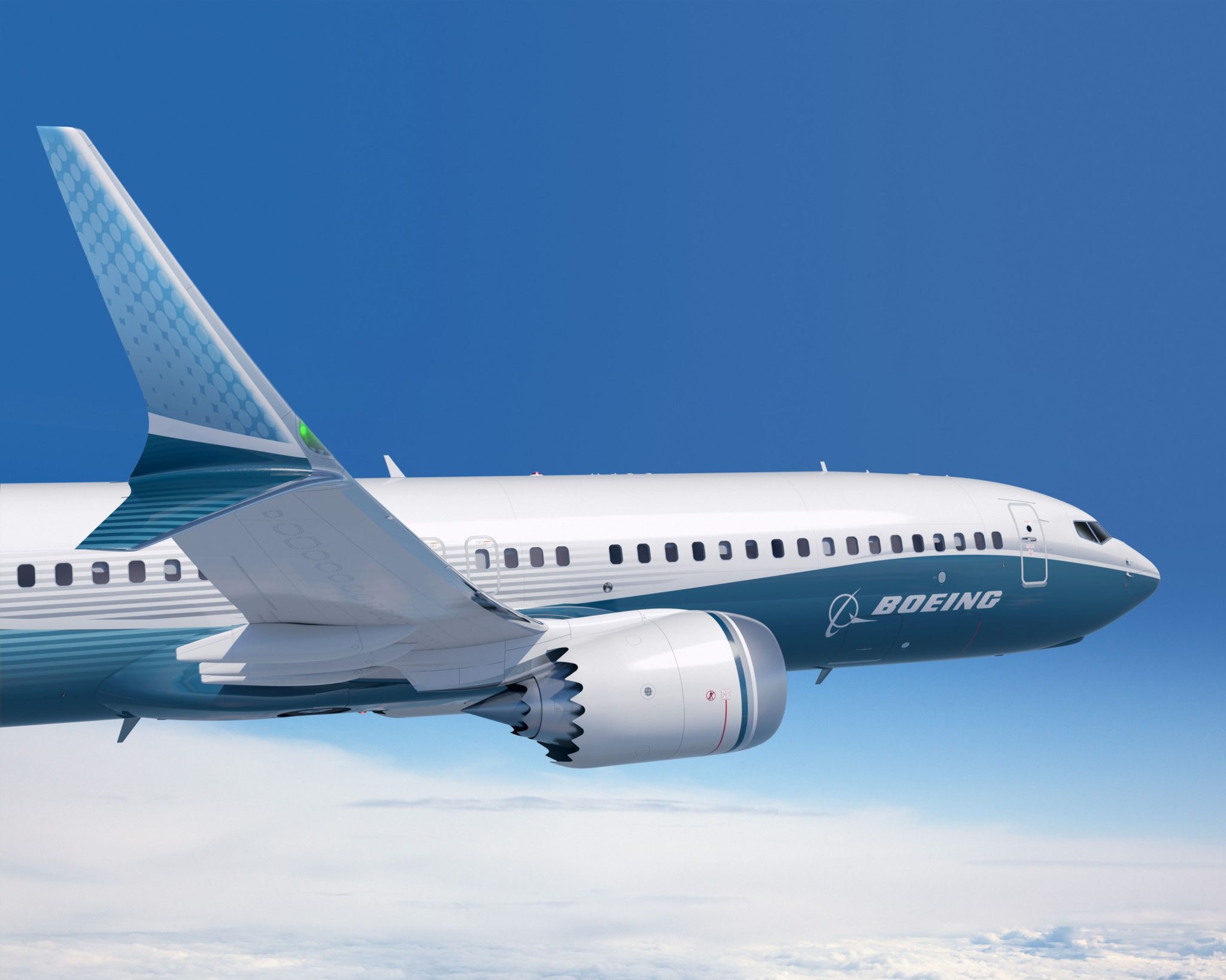
Figure 1. The Boeing MAX 8 which introduced the MCAS system to help with pitch stability. Source: Boeing.
Bjorn’s Corner: Supersonic transport revival, Part 14
By Bjorn Fehrm
November 9, 2018, ©. Leeham News: In last week’s Corner we compared the GE Affinity, the Mach 1.4 engine for the Arion AS2, to the engine of the Concorde when both propel a Mach 2 Supersonic Transport.
We could see an engine must be designed for working at Mach 2. The Olympus, now a 50-year-old design, was more efficient in propelling a Mach 2 SST than the hypermodern Affinity. Now we design a custom Mach 2.2 engine.

Figure 1. A Mach 2.2 suitable SST turbofan modeled with GasTurb. Source: GasTurb.
Bjorn’s Corner: Supersonic transport revival, Part 13
By Bjorn Fehrm
November 2, 2018, ©. Leeham News: In last week’s Corner we looked deeper into the fundamentals of the Mach 1.4 engine of Aerion’s AS2 SST, the GE Affinity.
Now we start looking at engines for a faster SST, up to the Mach 2.2 of the Boom Supersonic project.
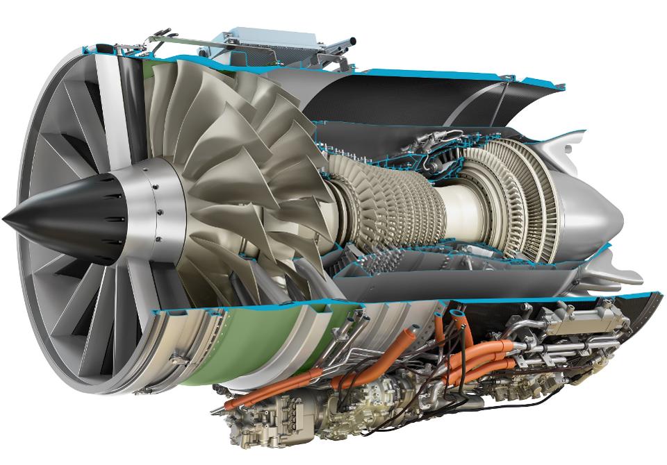
Figure 1. The GE Affinity medium bypass Turbofan for Aerion AS2. Source: GE.
Bjorn’s Corner: Supersonic transport revival, Part 12
October 26, 2018, ©. Leeham News: In the previous Corner we discussed the noise challenge an SST engine has. To be effective at Supersonic speed it needs a high Specific Thrust (a fast jet out the back) but this creates Takeoff and Landing noise.
We now look at some key data for SST engines.
Figure 1. The GE Affinity medium bypass Turbofan for Aerion AS2. Source: GE.
Bjorn’s Corner: Supersonic transport revival, Part 11
October 19, 2018, ©. Leeham News: In the last Corner we discussed the temperature challenges an SST engine faces.
Now we address an even larger problem for SST engines, the takeoff and landing noise.
Figure 1. The GE Affinity SST Turbofan for Aerion AS2. Source: GE Aviation.
Bjorn’s Corner: Supersonic transport revival, Part 10
October 12, 2018, ©. Leeham News: In the last Corner we discussed the challenges of the nacelle outlet for an SST (SuperSonic Transport). Now we will discuss SST engines and what are the key technical challenges for these engines.
We start this week by looking at some design constraints for the engine which we don’t have in Subsonic airliner engines.
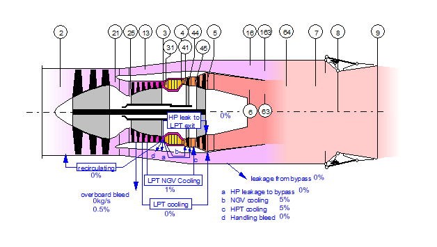 Figure 1. A generic mixed Turbofan SST engine with ConDi nozzle. Source: GasTurb. Read more