Leeham News and Analysis
There's more to real news than a news release.


Bjorn’s Corner: Aircraft drag reduction, Part 9

By Bjorn Fehrm
December 15, 2017, ©. Leeham Co: In the last Corner, we described how the Wright Brothers developed the first theory for propellers. It was based on their wing work and allowed them to design an efficient pair of propellers for their 1903 Wright Flyer.
We will now describe their first propelled flights, December 1903, and prepare for looking at the lift and drag of the aircraft.

Figure 1. The Wright Flyer is prepared for flight at Kitty Hawk, 17th December 1903. Source: Wright-Brothers.org.
Bjorn’s Corner: Aircraft drag reduction, Part 8
By Bjorn Fehrm
December 08, 2017, ©. Leeham Co: In the last Corner we described how the Wright Brothers developed their own engine, as there were no light engines on the market.
After understanding how to design wings, how to control the aircraft and having designed a suitable engine, the final item the Wrights needed was a working propeller.
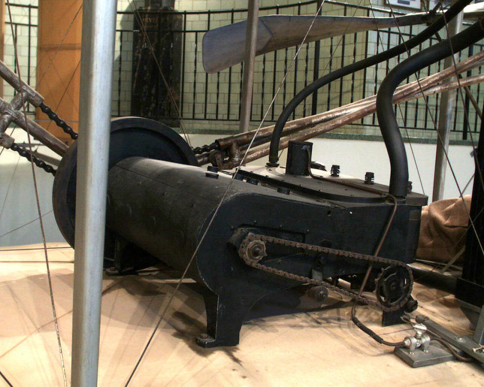
Figure 1. The Wright engine for its 1903 Flier, driving the pusher propeller in the background through bicycle chains. Source: Wright-Brothers.org.
Bjorn’s Corner: Aircraft drag reduction, Part 7
By Bjorn Fehrm
December 01, 2017, ©. Leeham Co: In previous Corners, we looked at how the Wright Brothers understood the wing aerodynamics and aircraft control.
We now describe how the Wright cracked the third nut keeping them from manned flight, propulsion.
When they had mastered the design of effective wings and control of their gliders (see previous Corners), the Brothers now worked on finding an engine and a functioning propeller.
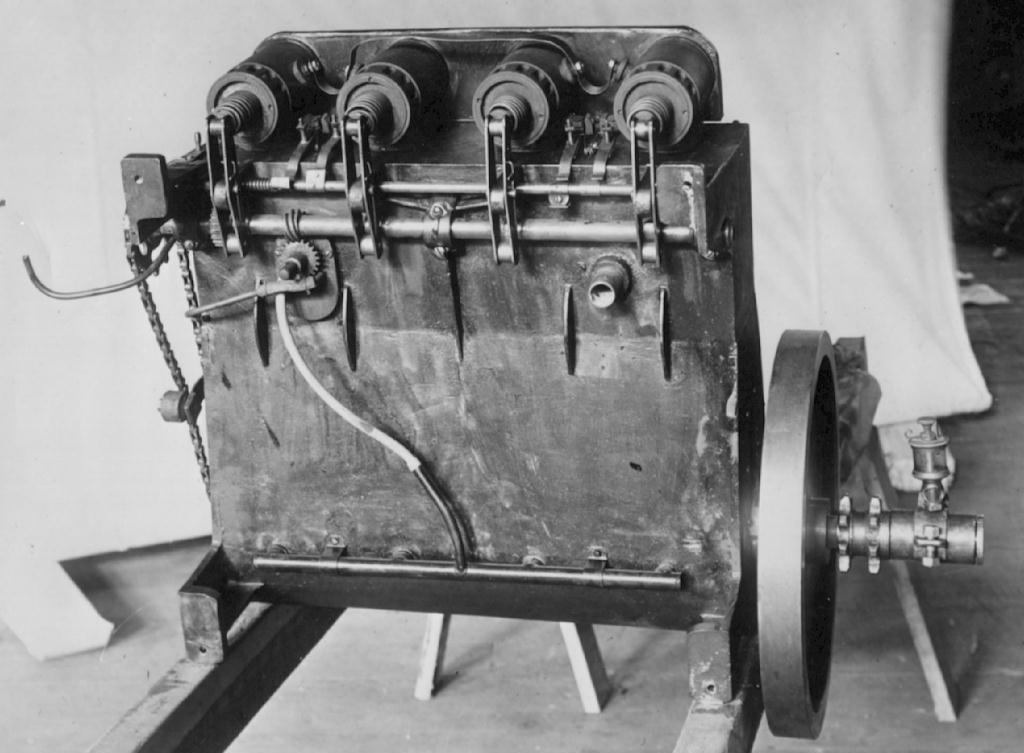
Figure 1. The Wright engine for its 1903 Flyer seen from the underside. Source: Wright-Brothers.org.
Bjorn’s Corner: Aircraft drag reduction, Part 6
By Bjorn Fehrm
November 24, 2017, ©. Leeham Co: In the last Corner, we described how the Wright Brothers obtained the aerodynamic data they needed to design gliders and aircraft.
But there was additional knowledge they needed: how to control an aircraft and how to drive it forward.
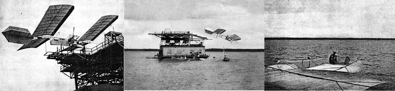
Figure 1. The Langley manned Aerodrome crashes into the Potomac River 7th of October 1903. Source: Wikipedia.
Bjorn’s Corner: Aircraft drag reduction, Part 5
November 17, 2017, ©. Leeham Co: In the last Corner, we described how the Wright Brothers (bicycle manufacturers in Dayton (OH)) decided to research their own aerodynamic data with the help of their own designed-and-built wind tunnel.
The wind tunnel was not more advanced than what had been done before. But their measurement system was. It built on their bicycle test setup, Figure 1.

Figure 1. The Wright Brothers’ arrangement for testing wing shapes on their bicycle autumn 1901. Source: NASA.
Bjorn’s Corner: Aircraft drag reduction, Part 4
By Bjorn Fehrm
October 27, 2017, ©. Leeham Co: In this and the following Corners, we will review the competition for first manned flight between Samuel Langley, high ranking scientist of Allegheny Observatory in Pittsburgh, and the Wright Brothers, bicycle manufacturers in Dayton, (OH).
We described in the last Corner how Langley researched airfoil characteristics with a giant whirling arm, built beside the Observatory. The Wright Brothers went another route; they built a wind tunnel in their workshop.
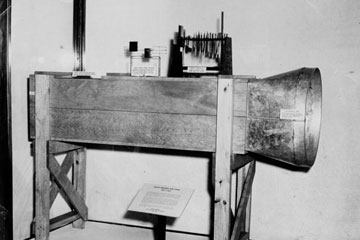
Figure 1. The wind tunnel built by the Wright Brothers. Source: Wikipedia.
Bjorn’s Corner: Aircraft drag reduction, Part 3
By Bjorn Fehrm
Nov. 3, 2017, ©. Leeham Co: In the previous Corner, we described how the aeronautical pioneers gradually uncovered what held them back from flying their gliders and airplanes successfully.
They knew they needed lift to fly. And to generate lift, birds taught them wings were needed. What they didn’t understand was why their winged contraptions lost speed and crashed when they threw themselves out from hills or towers. They didn’t understand the relationship between lift and drag.
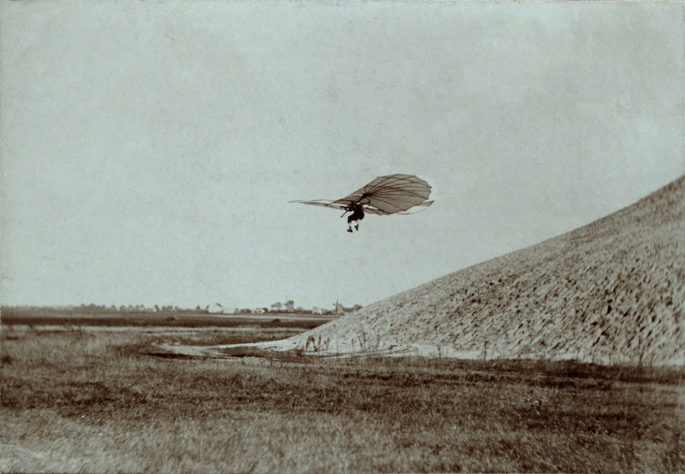
Figure 1. The first aviator, Otto Lilienthal, with his glider. Source: Wikipedia.
Bjorn’s Corner: Aircraft drag reduction, Part 2
By Bjorn Fehrm
October 27, 2017, ©. Leeham Co: After a detour over Airbus’ A330neo first flight last Friday, we now continue with aircraft drag. We divided drag in two classes last time: drag from size and drag from weight.
These drag effects were not discovered at the same time. To make it more informative, we will mix in how aircraft designers uncovered these drag types over time. It took them centuries to understand what held their flying devices back.
Figure 1. The first aviator, Otto Lilienthal, with his glider 1895. Source: Wikipedia.
Bjorn’s Corner: Airbus A330neo flight test starts
By Bjorn Fehrm
October 20, 2017, © Leeham Co, Toulouse: The Airbus A330neo flew its first flight yesterday. The aircraft lifted off from Toulouse Blagnac Airport in front of invited airline customers, suppliers and media. It landed after a successful four-hour mission.
We’ll take the opportunity to look at the A330neo changes and its flight test program. We also look at the drag reducing changes from A330ceo to A330neo.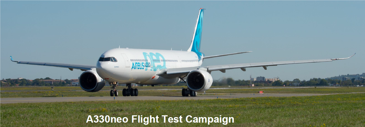
Read more
Bjorn’s Corner: Aircraft drag reduction
By Bjorn Fehrm
October 06, 2017, ©. Leeham Co: In the last several Corners, we wrote about research around laminar flow for aircraft. It’s research to lower the aircraft’s drag. Why is this important? How large are the different drag types and what can be done about them?
To find out, we will spend some Corners looking into the drag of an aircraft and what is done to optimize the drag for different aircraft types.

Figure 1. The “Blade” equipped A340-300, researching into lower drag for an airliner. Source: Airbus.