Leeham News and Analysis
There's more to real news than a news release.


Bjorn’s Corner: Why e in ePlane shall stand for environment. Part 1. Hype versus reality.
December 13, 2019, ©. Leeham News: The first all-electric commercial aircraft, a Harbor Air DHC-2 Beaver, flew over the Fraser River near Vancouver in the week (Figure 1). It was powered by a magniX electric engine fed with energy from batteries.
Despite this progress, this Corner series is about why the e in our future ePlanes should stand for environment and not electric.

Figure 1. Harbour Air seaplane flying with a magniX electric engine feed by batteries. Source: magniX.
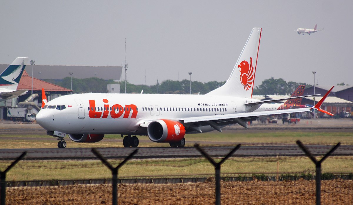
Bjorn’s Corner: Analysing the Lion Air JT610 crash, Part 6.

By Bjorn Fehrm
December 6, 2019, ©. Leeham News: We now finalize the series about the Lion Air JT610 crash by analyzing the changes Boeing has made to the aircraft to avoid further problems with MCAS (Maneuver Characteristics Augmentation System).
The changes bring MCAS to the level it should have had from entry into service and in some aspects further.
Bjorn’s Corner: Analysing the Lion Air JT610 crash, Part 5.
November 29, 2019, ©. Leeham News: We continue the series about the Lion Air JT610 crash by now analyzing the final part of the flight.
We try to understand what changed when the First Officer took over the flying from the Captain and why the aircraft subsequently crashed.
Bjorn’s Corner: Analysing the Lion Air JT610 crash, Part 4.
By Bjorn Fehrm
November 22, 2019, ©. Leeham News: We continue the series on analyzing the Lion Air JT610 crash by analyzing MCAS in more depth before we go to the final part of the flight.
We look at what was wrong with the initial version of MCAS, the augmentation system that caused JT610 to crash and what has changed in the updated version. Read more
Bjorn’s Corner: Analysing the Lion Air JT610 crash, Part 2.
November 8, 2019, ©. Leeham News: We started the series on analyzing the Lion Air JT610 crash based on the final crash report last week by looking at what went wrong with the aircraft’s Angle of Attack sensors.
Now we continue with looking at why an MCAS system is needed in an aircraft like the Boeing 737 MAX and why a correctly designed MCAS is not an irrational addition to the aircraft.
Bjorn’s Corner: Analysing the Lion Air 737 MAX crash, Part 1.
By Bjorn Fehrm
November 1, 2019, ©. Leeham News: We start the series on analyzing the Lion Air 737 MAX crash by looking at what went wrong in the aircraft. It’s important to understand MCAS is not part of what went wrong. It worked as designed during all seven Lion Air flights we will analyze in this series.
It was a single sensor giving a faulty value that was wrong with these aircraft. How a single faulty sensor could get MCAS to doom the JT610 flight (called LNI610 in the report) is something we look into later in the series. Now we focus on why the sensor came to give a faulty value for five out of seven Lion Air flights and how these flights could be exposed to two different sensor faults.
Bjorn’s Corner: Analysing the 737 MAX crashes
October 25, 2019, ©. Leeham News: To better understand what went wrong in the Boeing 737 MAX crashes I have over the last half-year run Corner series around aircraft Pitch stability and Aircraft Flight Control systems and how these attack the problems of today’s airliners need for stable characteristics over a very wide flight envelope.
With this as a backgound, we will now in a series of Corners go into the Lion Air final crash report which is issued today, to understand what happened and why.
Bjorn’s Corner: Fly by steel or electrical wire, Part 13
October 18, 2019, ©. Leeham News: In our series about classical flight controls (“fly by steel wire”) and Fly-By-Wire (FBW or “fly by electrical wire”) we continue our discussion of pitch stability augmentation systems when we have a mechanical (“fly by steel wire”) pitch control system.
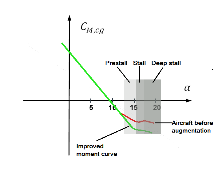
Figure 1. The pitch moment curve of a modern airliner. Source: Leeham Co.
Bjorn’s Corner: Fly by steel or electrical wire, Part 12
October 11, 2019, ©. Leeham News: In our series about classical flight controls (“fly by steel wire”) and Fly-By-Wire (FBW or “fly by electrical wire”) we continue our discussion of pitch stability augmentation systems when we have a mechanical (“fly by steel wire”) pitch control system.
Figure 1. The typical pitch moment curve of a modern airliner. Source: Leeham Co.
Bjorn’s Corner: Fly by steel or electrical wire, Part 11
October 4, 2019, ©. Leeham News: In our series about classical flight controls (“fly by steel wire”) and Fly-By-Wire (FBW or “fly by electrical wire”) we now discuss pitch stability augmentation systems when we need to improve the pitch characteristics of a mechanical (“fly by steel wire”) pitch control system.
Figure 1. The pitch moment curve of a modern airliner when circling before landing. Source: Leeham Co.