Leeham News and Analysis
There's more to real news than a news release.


Bjorn’s Corner: Fly by steel or electrical wire, Part 6

By Bjorn Fehrm
August 30, 2019, ©. Leeham News: In our series about classical flight controls (“fly by steel wire”) and Fly-By-Wire (FBW or “fly by electrical wire”) we now discuss the flight control laws which are used for Classical flight controls and FBW systems.
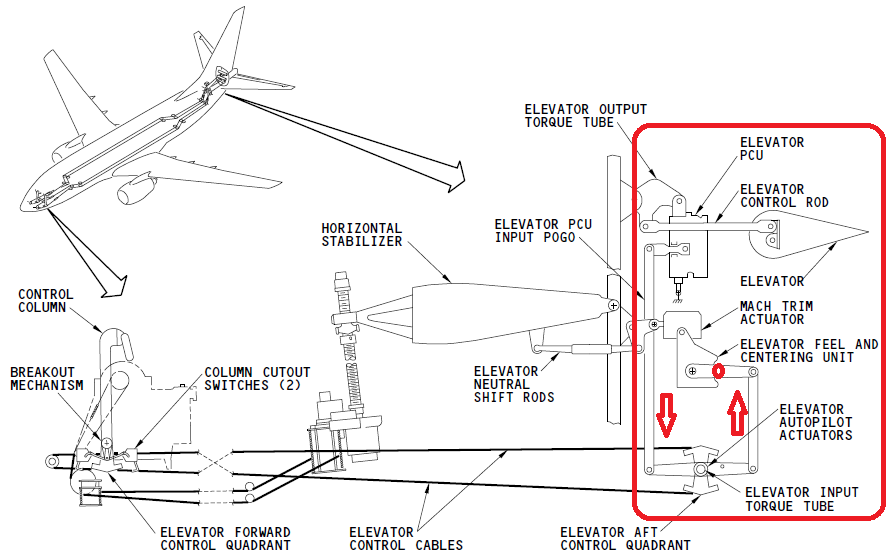
Figure 1. The Boeing 737 artificial feel unit operating over right rod increases roller pressure on feel unit cam, by it making displacement of both left and right rods over Elevator Control Quadrant harder (the arrows depict an elevator up command). Source: Boeing.
Bjorn’s Corner: Fly by Steel or Electrical wire, Part 5
By Bjorn Fehrm
August 23, 2019, ©. Leeham News: In our series about classical flight controls (“fly by steel wire”) and Fly-By-Wire (FBW or “fly by electrical wire”) we now look at practical implementations after discussing the authority of the flight control system last week.
As before we compare the classical 737 system to the A320 FBW system.

Figure 1. The two mechanical control pitch systems of the 737 are visible in the upper left. Each side has a complete system shown at the lower part of the figure (except for the trim which has dual wire sets but one actuator motor/drum). Source: Boeing.
Bjorn’s Corner: Fly by steel or electrical wire, Part 4
By Bjorn Fehrm
August 16, 2019, ©. Leeham News: In our series about classical flight controls (“fly by steel wire”) and Fly-By-Wire (FBW or “fly by electrical wire”) we this week discuss the Flight Control System’s authority to execute maneuvers by its different parts and why the authority of these parts is a fundamental parameter when designing the system.
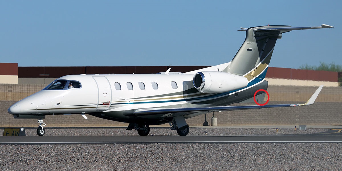
Figure 1. Embraer Phenom 300’s Yaw damper rudder. Source: Embraer.
Bjorn’s Corner: Fly by steel or electrical wire, Part 3
By Bjorn Fehrm
August 9, 2019, ©. Leeham News: In our series about classical flight controls (“fly by steel wire”) and Fly-By-Wire (FBW or “fly by electrical wire”), we this week turn to the actual Flight control system after covering the infrastructure needs last week. We could see the FBW required a higher redundancy Hydraulic and Electrical infrastructure. Why we will come to.
Now we look at the control principles for classical control systems like the Boeing 737 system and FBW system like the Airbus A320 system.
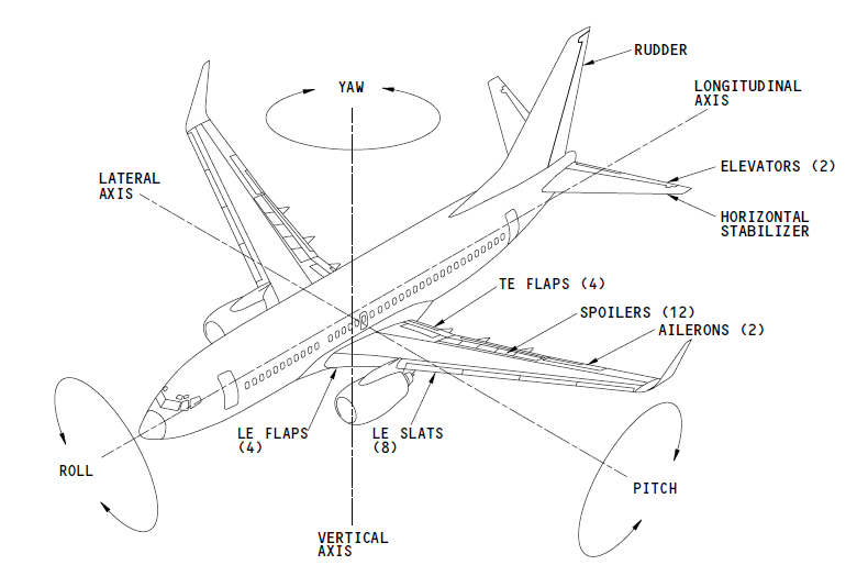
Figure 1. The control axis and control surfaces of a 737. Source: Boeing.
Bjorn’s Corner: Fly by steel or electrical wire, Part 2
By Bjorn Fehrm
July 25, 2019, ©. Leeham News: In our series about classical flight controls (“fly by steel wire”) and Fly-By-Wire (FBW or “fly by electrical wire”) this week we cover the difference in system infrastructure the two controls methods call for.
We will use the Boeing 737 as the classical control example and the Airbus A320 as the FBW example.

Bjorn’s Corner: Fly by steel or electrical wire?
By Bjorn Fehrm
July 25, 2019, ©. Leeham News: Last week’s Corner which dealt with Airbus’ issue with an updated A321neo Fly By Wire (FBW) and how it was unrelated to the issue of the Boeing 737 MAX, gives a good segue to a Corner series about the possibilities of FBW versus classical flight controls when it comes to tuning an airliner’s flight characteristics.
The two different control principles present the designer with very different challenges and possibilities.
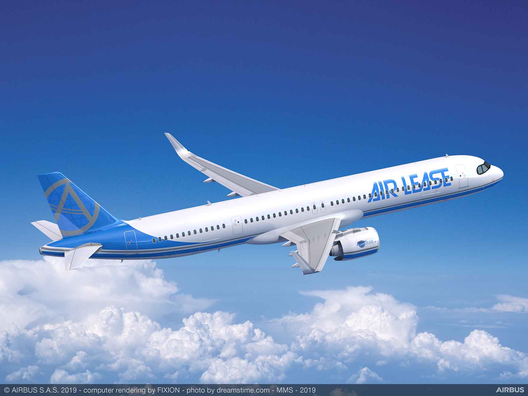
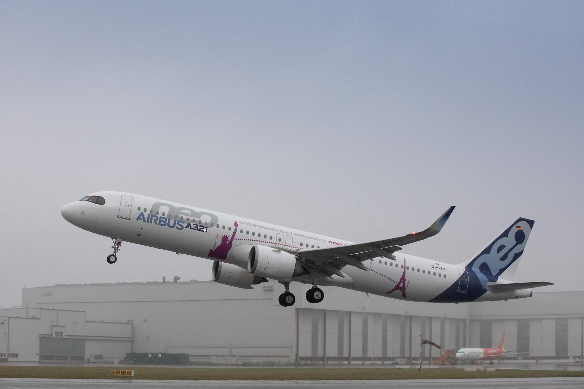
The Fly-By-Wire Airbus A321XLR. Source: Airbus.
Bjorn’s Corner: Airbus’ A321neo has a pitch-up issue (now with a second update)
By Bjorn Fehrm
July 19, 2019, ©. Leeham News: The European Aviation Safety Agency EASA has issued an Air Worthiness Directive (AD) to instruct operators of the Airbus A321neo of a Pitch instability issue.
EASA writes “excessive pitch attitude can occur in certain conditions and during specific manoeuvres. This condition, if not corrected, could result in reduced control of the aeroplane.”
We analyze how this is similar or different to the Boeing 737 MAX pitch instability issues.
NOTE 2: We have got a further update from Airbus, see below.
Bjorn’s Corner: Kjos departure signals changes at Norwegian
By Bjorn Fehrm
July 12, 2019, ©. Leeham News: Norwegian Air Shuttles’ (Norwegian) founder and CEO for 17 years, Bjorn Kjos stepped down yesterday. Over the last year the CFO, Board chairman and now the CEO have changed.
This signals a change in strategy for Norwegian. The new management is focused on halting growth and cutting costs. Norwegian must now consolidate itself to profitability.
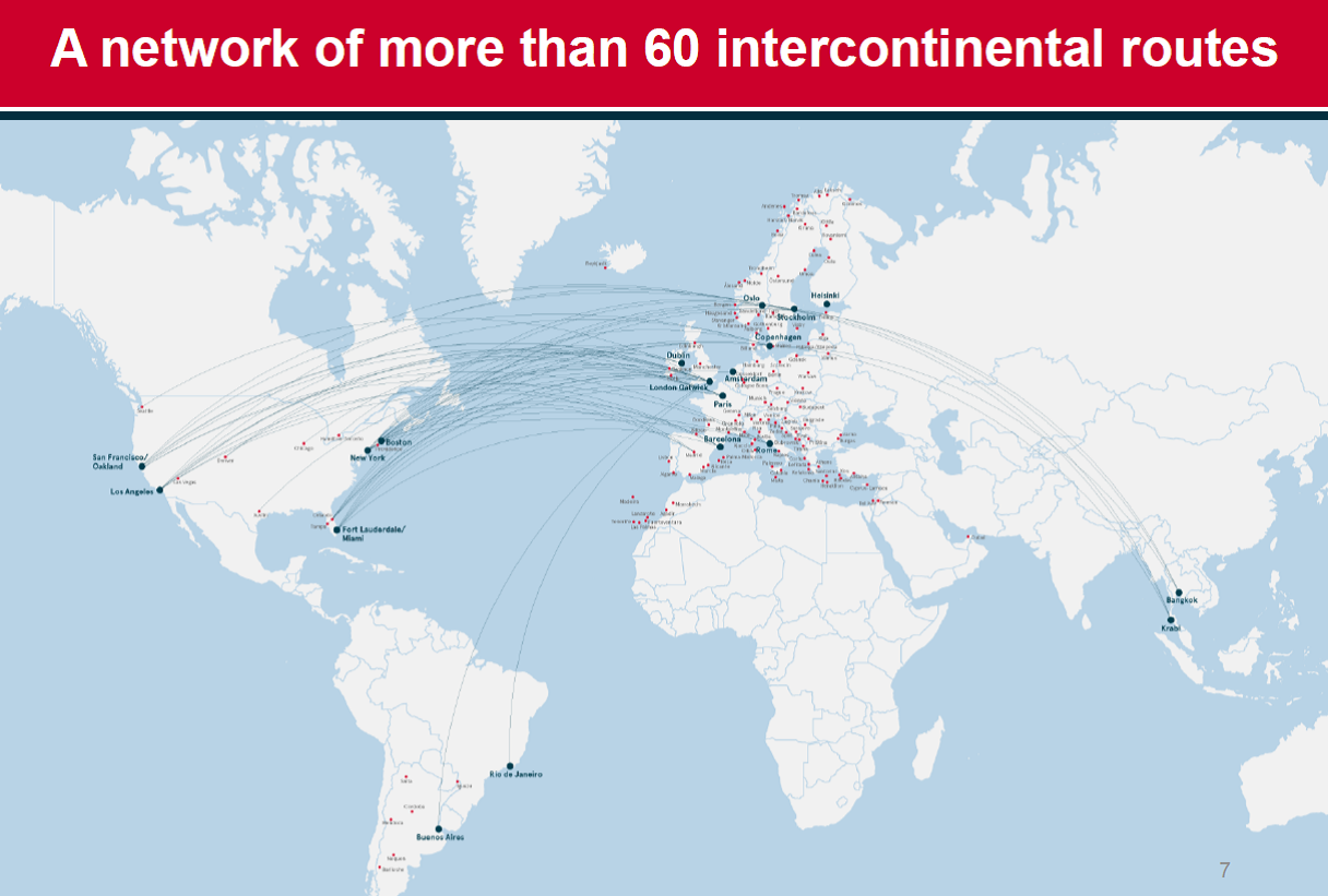
Figure 1. Norwegians Intercontinental network spring 2019. Source: Norwegian.
Bjorn’s Corner: Cutting corners in aerospace costs a fortune
By Bjorn Fehrm
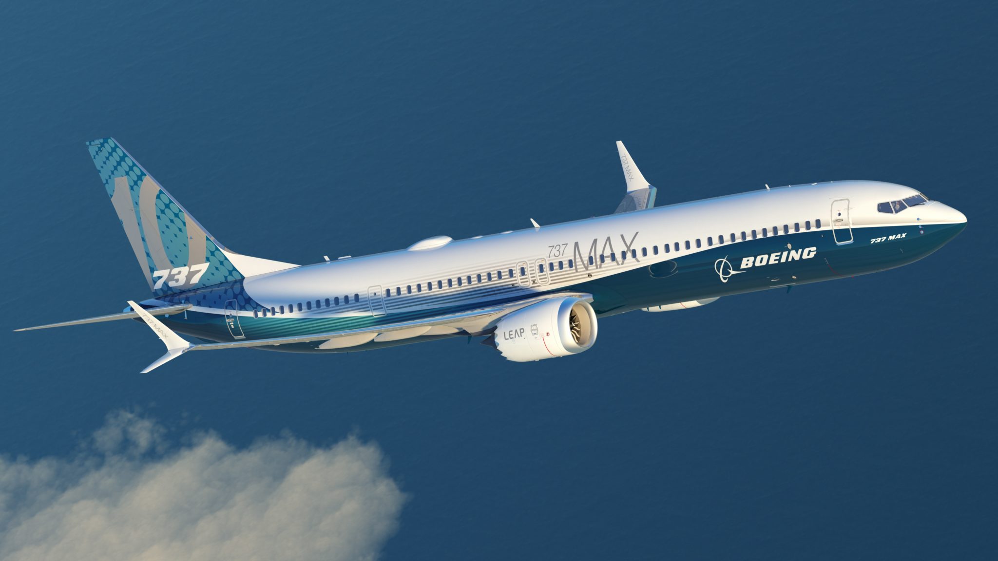
July 05, 2019, ©. Leeham News: It seems more and more likely the 737 MAX grounding will go well beyond six months and it can approach nine months to a year depending on developments in the next months.
The costs to Boeing for the MAX debacle are now approaching the costs of a new aircraft development.
Bjorn’s Corner: New pitch trim issue forces further changes to 737 MAX software
By Bjorn Fehrm
June 28, 2019, ©. Leeham News: “The Federal Aviation Administration has asked The Boeing Company to address, through the software changes to the 737 MAX that the company has been developing for the past eight months, a specific condition of flight, which the planned software changes do not presently address.”
This is the text of an 8-K filing Boeing issued to the stock market two days ago. Here is what it means.