Leeham News and Analysis
There's more to real news than a news release.


Bjorn’s Corner: Laminar flow aircraft, Part 2.
October 06, 2017, ©. Leeham Co: We introduced the Airbus “Blade” laminar flow research program in the last Corner. Now we continue to look into what this research is all about.
We will explain the difference between laminar and turbulent flow (really, laminar and turbulent “boundary layer” flow) and discuss some of the work that has been done with laminar flow structures.

Figure 1. The “Blade” equipped A340-300. Source: Airbus.
Read more
Bjorn’s Corner: Laminar flow aircraft

By Bjorn Fehrm
September 29, 2017, ©. Leeham Co: Airbus flew its “Blade” laminar flow research aircraft for the first time this week. It’s a project in the European Clean Sky research program.
The “Blade” aircraft is a modified Airbus A340-300, where the outer wings have been replaced with special laminar flow wing sections. We will spend a couple of Corners to understand why this research is done and why it’s important.
Figure 1. The “Blade” equipped A340-300. Source: Airbus.
Read more
Bjorn’s Corner: Electric aircraft, Part 13
By Bjorn Fehrm
September 22, 2017, ©. Leeham Co: After 12 articles about electric aircraft, it’s time to wrap up. We will go through what we have learned and discuss future developments.
Our designs were aimed for the next decade and the result was sobering. Electric aircraft have important challenges to traverse. As had electric cars, and they have turned the corner.

Figure 1. Idea for future aircraft that could use electric propulsors. Source: NASA.
Bjorn’s Corner: Electric aircraft, Part 12
By Bjorn Fehrm
September 15, 2017, ©. Leeham Co: Last week we compared the energy economics of our 10-seater electric commuter to an equivalent commuter with gas turbine power.
Now we dig a bit deeper in the operational costs of the two aircraft. Is the electric commuter cheaper to operate over short sectors than a gas turbine driven variant? For the energy costs, it could be the fact. What about other operational costs?
The commuter designs we discuss would be similar to the Zunum Aero 10-seater commuter in Figure 1.
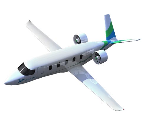
Figure 1. Zunum Aero’s short-haul turbofan commuter. Source: Zunum Aero.
Bjorn’s Corner: Electric aircraft, Part 11
By Bjorn Fehrm
September 8, 2017, ©. Leeham Co: After our definition of an-all electric 10-seater for Ultra short-haul flying in last Corner, we now compare its economics to a gas turbine propelled design.
Our designs have the Zunum Aero 10-seater commuter in Figure 1 as reference.
Figure 1. Zunum Aero’s short-haul turbofan commuter. Source: Zunum Aero.
Bjorn’s Corner: Electric aircraft, Part 10
By Bjorn Fehrm
September 1, 2017, ©. Leeham Co: in the nine previous Corners, we looked at 50-seat regional jets and turboprops with hybrid electric propulsion systems.
We have seen that at the state of technology until the mid-next decade, such aircraft have dubious efficiency. The hybrid propulsion chain weighs too much, and can at best match the propulsion efficiency of gas turbine based aircraft when one includes any airframe gains that can be made.
We will now finish the series by looking at a pure electric concept, designed for extremely short-haul routes. The Zunum Aero 10-seat commuter in Figure 1 will be our reference for such a design.
Figure 1. Zunum Aero’s short-haul turbofan commuter. Source: Zunum Aero.
Read more
Bjorn’s Corner: Electric aircraft, Part 9
By Bjorn Fehrm
August 25, 2017, ©. Leeham Co: We finished the weight sizing of the hybrid propulsion system for our 50-seat regional turboprop in the last Corner. Now we go a bit more into detail. There are additional parts needed in the system that we skipped over last time.
We discuss the impact of these additional components and any gains we can make with the aircraft configuration.
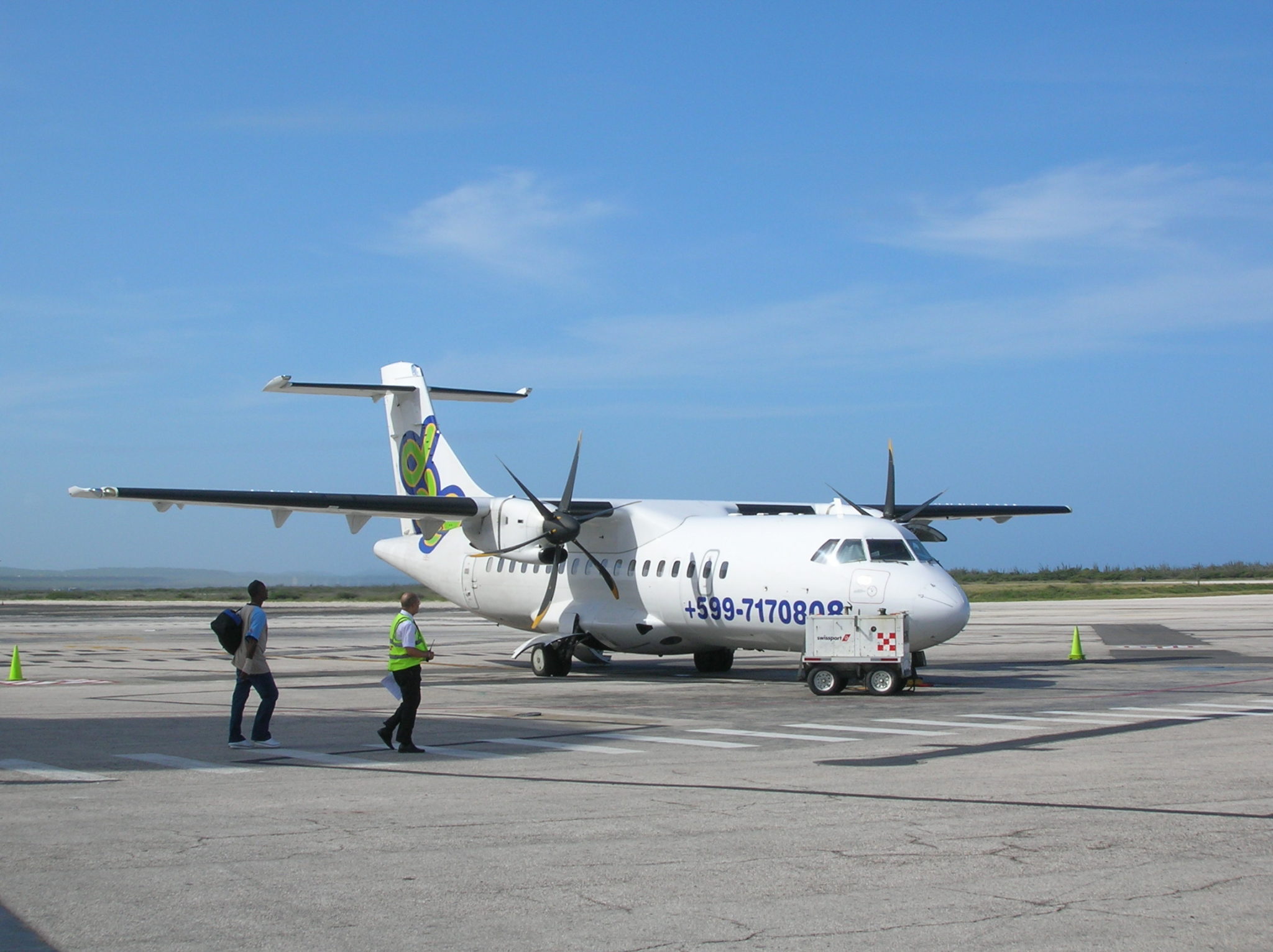
Figure 1. ATR42-600 serves as a template for our 50-seat regional turboprop. Source: ATR.
Bjorn’s Corner: Electric aircraft, Part 8
By Bjorn Fehrm
August 18, 2017, ©. Leeham Co: In this Corner, we will finish the design of the hybrid propulsion system for our 50-seat regional turboprop. We use the ATR42-600 as a reference, as before (Figure 1).
We found an acceptable redundancy concept in the previous Corner, with an APU+generator+battery as backup power source. Now we will finish the design of the hybrid propulsion chain and compare with the original turboprop propulsion.
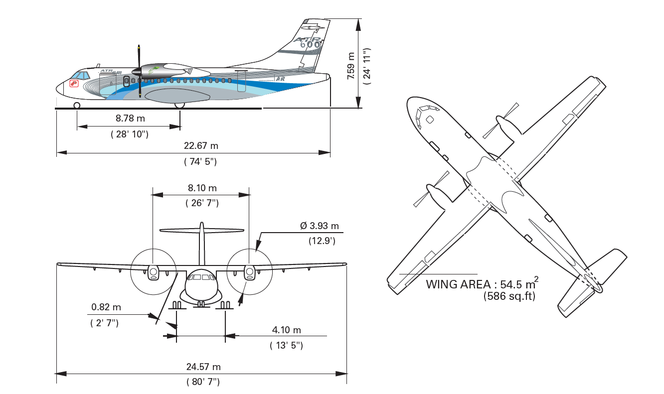
Figure 1. ATR42-600 serves as a template for our 50-seat regional turboprop. Source: ATR.
Read more
Bjorn’s Corner: Electric aircraft, Part 7
By Bjorn Fehrm
August 11, 2017, ©. Leeham Co: In this Corner, we will design the hybrid propulsion system for our 50-seat regional turboprop. We could see in previous Corners that we can’t use batteries as a backup for our gas turbine core and main generator.
The battery gets too heavy as the specific power weight of a battery is simply too low. We will now design a hybrid power chain with a different redundancy concept.
Figure 1. ATR 42-600 serves as a template for our 50-seat regional turboprop. Source: ATR.
Bjorn’s Corner: Electric aircraft, Part 6
By Bjorn Fehrm
August 03, 2017, ©. Leeham Co: In our search for an electric regional aircraft configuration, we found that a jet aircraft requires too high power levels. The higher speeds of a jet aircraft take the power levels beyond what we can handle with an electric hybrid propulsion system.
Our ambition is to transport 50 passengers on a regional network. For networks which have sectors around 200-300nm, the turboprop is the preferred regional aircraft. We will now re-direct our hybrid regional aircraft project to this market segment.
Figure 1. An ATR 42-600 48 seat regional turboprop. Source: Wikipedia.