Leeham News and Analysis
There's more to real news than a news release.


Bjorn’s Corner: Why e in ePlane shall stand for environment, Part 11. More electric aircraft.
February 28, 2020, ©. Leeham News: We now look at technology developments that make sense, and can deliver real improvements in the near future.
We start in this Corner with what more electric aircraft and engines can bring.

Figure 1. Boeing’s 787, the first more electric airliner. Source: Boeing.
Bjorn’s Corner: Why e in ePlane shall stand for environment, Part 9. Hydrogen, cont.
February 14, 2020, ©. Leeham News: Last week we started looking at hydrogen as an alternative energy source for our air transport system. We discussed the use of hydrogen as a direct fuel replacement to jet fuel, burning the hydrogen in the combustor of the aircraft’s turbofans.
Hydrogen works fine as a fuel for the turbofan but it has challenges in its onboard storage, it’s handling and production. Good reader discussions followed around those problems. Now we look at hydrogen as a fuel in a fuel cell/electrical motor propulsion system.
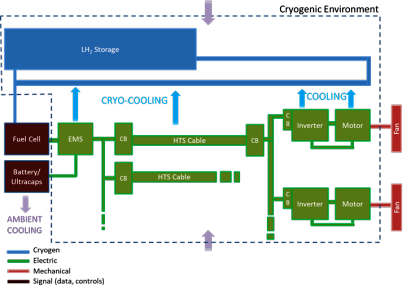
Figure 1. Components of a fuel cell-based aircraft propulsion system. Source: NASA.
Bjorn’s Corner: Why e in ePlane shall stand for environment, Part 8. Hydrogen.
February 7, 2020, ©. Leeham News: After discussing established ways of improving the environmental footprint of our air transport system and highlighting the challenges involved with an electric/hybrid route we now look at hydrogen as an alternative energy source.
We will quote from a study series made by Airbus at the turn of the century. It’s today 20 years old but its ideas and conclusions are more relevant than ever.

Figure 1. Hydrogen powered airliner from Airbus study. Source: Airbus study presentation.
Bjorn’s Corner: Why e in ePlane shall stand for environment, Part 5. Distributed propulsion.
January 17, 2020, ©. Leeham News: We continue our series why e in ePlane shall stand for environment and not electric, where we now examine the gains with electric/hybrid distributed propulsion systems.
We started last week with the type of boundary layer ingesting aft fans shown in Figure 1. Now we continue with wing mounted distributed propulsors.
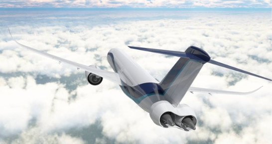
Figure 1. Boundary-Layer Ingestion aft fans, driven by electric motors. Source: JADC.
Bjorn’s Corner: Why e in ePlane shall stand for environment, Part 3. Open rotor revisited.
January 3, 2020, ©. Leeham News: We continue our series why e in ePlane shall stand for environment and not electric.
Our target is to lower air transport’s environmental footprint and we can achieve this more efficiently by using established technologies. As an example, I will describe a very promising concept that has fallen out of focus due to the hype around everything hybrid and electric.

Figure 1. The Clean Sky IRON project aircraft with an Unducted Single Fan (USF) propulsion. Source: Clean Sky.
Read more
Bjorn’s Corner: Why e in ePlane shall stand for environment, Part 2. Fly shorter routes.
December 20, 2019, ©. Leeham News: We continue our series why e in ePlane shall stand for environment and not electric.
If our target is to lower the environmental footprint from air transport we must have a target that focuses just that, lowering the CO2 load from our airliners. Electric or Hybrid-electric aircraft are not the most efficient way to achieve this. There are better ways to this target.

Figure 1. A FlightRadar24 picture of our daily airline routes. Source: FR24.
Bjorn’s Corner: Why e in ePlane shall stand for environment. Part 1. Hype versus reality.
December 13, 2019, ©. Leeham News: The first all-electric commercial aircraft, a Harbor Air DHC-2 Beaver, flew over the Fraser River near Vancouver in the week (Figure 1). It was powered by a magniX electric engine fed with energy from batteries.
Despite this progress, this Corner series is about why the e in our future ePlanes should stand for environment and not electric.

Figure 1. Harbour Air seaplane flying with a magniX electric engine feed by batteries. Source: magniX.
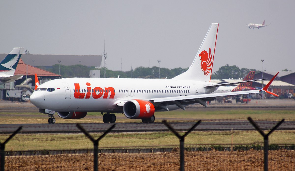
Bjorn’s Corner: Analysing the Lion Air JT610 crash, Part 6.

By Bjorn Fehrm
December 6, 2019, ©. Leeham News: We now finalize the series about the Lion Air JT610 crash by analyzing the changes Boeing has made to the aircraft to avoid further problems with MCAS (Maneuver Characteristics Augmentation System).
The changes bring MCAS to the level it should have had from entry into service and in some aspects further.
Bjorn’s Corner: Analysing the Lion Air JT610 crash, Part 5.
November 29, 2019, ©. Leeham News: We continue the series about the Lion Air JT610 crash by now analyzing the final part of the flight.
We try to understand what changed when the First Officer took over the flying from the Captain and why the aircraft subsequently crashed.
Bjorn’s Corner: Analysing the Lion Air JT610 crash, Part 4.
By Bjorn Fehrm
November 22, 2019, ©. Leeham News: We continue the series on analyzing the Lion Air JT610 crash by analyzing MCAS in more depth before we go to the final part of the flight.
We look at what was wrong with the initial version of MCAS, the augmentation system that caused JT610 to crash and what has changed in the updated version. Read more