Leeham News and Analysis
There's more to real news than a news release.

 Leeham News and Analysis
- Bjorn’s Corner: New engine development. Part 5. Turbofan design problems April 26, 2024
- Airbus 1Q2024 results: Airbus CEO: “A350 in-service experience drives positive reputation and orders” April 25, 2024
- A350-1000 or 777-9? Part 3 April 25, 2024
- Boeing CEO promises company is turning around…again April 24, 2024
- Solid start for stand-alone GE Aerospace despite cuts to LEAP output April 23, 2024
Bjorn’s Corner: Sustainable Air Transport. Part 36. Battery Management.

By Bjorn Fehrm
September 9, 2022, ©. Leeham News: Over the last weeks, we have discussed the cells that make up the battery system for an eVTOL.
The battery system has 10,000 cells or more. All these must, on an individual level, be managed to ensure they operate inside their allowed values. The Battery Management System, BMS, has this responsibility. It’s one of the most critical safety systems in an eVTOL.
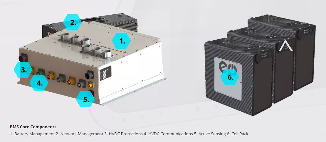
Figure 1. The Battery Management System and battery packs from EP Systems. Source: EP Systems.
The Battery Management System
We could see that we need about 10,000 Li-Ion cells to produce an eVTOl battery of 150 kWh if we use cylindrical cells. These 10,000 cells are all individuals with varying electrical characteristics, such as different internal resistance to charge and discharge currents. It means the cells heat up differently when charged or during use.
A battery cell must at all times be operated inside its Safe Operating Area, SOA. Figure 2 shows an SOA for a generic Li-Ion cell.

Figure 2. The Safe Operating Area of a Li-Ion cell. Source: elithion.
We will not go into detail about what the different acronyms mean, but we can see there are three axes on the graph, Voltage (vertical axis, from 2.9V to 4.2V), Current (charge up to 0.5 C, discharge to 1C), and Temperature (from +60°C to below -20°C).
We also see that the cells’ operation must be kept inside the areas connecting Voltages, Currents, and Temperatures. For example, this cell will only accept +40°C or lower when being charged at 0.5C, and the Voltage applied to the cell must be less than 4.2V for high charge currents (the CL area is sloping down from 4.2V).
The system that shall ensure that each of the 10,000 cells stays within their SOA is the Battery Management System, BMS. For aeronautical propulsion battery use, only the most sophisticated BMS will do.
Charging limits and Balancing
During charging, the BMS cooperates with the external battery charger to ensure no single cell gets charged outside their SOA. As cells charge a bit differently, one cell in a battery module can reach the maximum allowed charge before other cells. A further charge would make this cell exceed its maximum charge level. The BMS then has to tell the charger to stop charging.
To allow a full charge of all cells, the BMS can dissipate a bit of the fully charged cell’s energy or reduce the charge currents individually per cell before reaching full charge for the cells. Otherwise, the batter module is unbalanced. That means one or several cells are at 100% SOC, whereas others could be at 95% down to 90% SOC. A BMS, therefore, has balancing functions at charging to get the battery close to a 100% SOC for each cell.
When the battery is new, presorting the cells has rejected those that differ over a limit compared with others. As the cells age, the spread in parameters will increase, and balancing the 10,000 cells to reach an optimal SOC for the system gets more and more important.
Discharge limits
At discharge, the BMS monitors the discharge current for each module, its Voltage, and the temperature for each cell.
The current monitoring ensures cells are not exceeding their peak (for a shorter time) or continuous current discharge rate (we can see the maximum current for this cell is Voltage-dependent). If this happens, a warning is given to the VTOL at first, then, ultimately, the module or pack is cut off from the system by the BMS.
As the battery nears lower SOCs, cells must not go below their minimum Voltage (2.9V in this case). If they do, the cells get damaged and will cause problems in the following charge and flight cycles.
Should the temperature limit area HD be reached, the BMS will either reduce the available current from the module or command a switch-off from the system. Before reaching HD, the BMS has sent warning information to the propulsion system for the VTOL, saying Module XX or Pack YY is close to the temperature limit, reduce power draw, or separate the pack from the system.
State Of Health and Logging
The BMS closely monitors the cells, modules, and packs. It measures Voltages, currents, and temperatures. Through simple math, it keeps track of the changes of all these parameters and aggregated parameters. It can thus track the full charge SOC, the changes in internal resistance, any deterioration of parameters outside the normal, etc.
This data logging and calculations form part of the battery systems State Of Health (SOH), and it is continuously reported to the central monitoring systems of the VTOL. Through it, the pilots, mechanics, and the operator can monitor the energy system’s development and decide the VTOL individual’s performance level and its range.
The basic parameters are also logged for later analysis as part of the regulatory logging required to analyze any safety-related aircraft issues.
I am curious on the battery management aspect in how a BMC works.
Most of my work was with lead acid and those were managed based on maximum current they would take and the whole set was throttled back as it reached full voltage. Lead Acid were not picky of course.
But to manage thousands of cells you would have to have a wire pair to each one and then a method of jumping some of the current around each cell to reach a balance for all the cells.
Dropping a block of cells out means a way to bypass those as well so we are talking some serious wiring along with the control of the bypass line(s).
https://www.youtube.com/watch?v=q4wDa_m9-8E
For the finer internal detail
Phew, I got some reading ahead of me.
That is exactly what battery cell management and balancing integrates circuilts work. They will measure the voltage of each cell and often switch to apply a small balancing current.
This is a data sheet for the Infineon TLE9012DQU
https://www.infineon.com/dgdl/Infineon-TLE9012DQU-DataSheet-v01_00-EN.pdf?fileId=8ac78c8c7e7124d1017f0c3d27c75737
I think the problem of connecting up each cell is not so onerous given that a chip can handle say 12 series coonected cells and that the chips network.
There is a concept of smart cells where each cell or pouch has its own chip to provide temperature and voltage measurement as well as a cell balance switch and addressable networking.
https://www.researchgate.net/profile/Sebastian-Steinhorst-2/publication/275256987_Smart_Cells_for_Embedded_Battery_Management/links/553624700cf268fd00160e27/Smart-Cells-for-Embedded-Battery-Management.pdf?origin=publication_detail