Leeham News and Analysis
There's more to real news than a news release.


No new design needed for turboprops, says Bombardier
- Part 1, ATR, appeared last week. Today’s interview with Bombardier completes the two-part series.
Subscription Required
Introduction
April 4, 2017, © Leeham Co.: Bombardier doesn’t think a new, clean-sheet turboprop aircraft is needed any time soon, a position that stands in contrast with rival ATR.

Bombardier Q400.
Ross Mitchell, VP Commercial for BBD, believes the Q400 covers the turboprop segment from 70 to 90 seats and its operational flexibility covers everything airlines need today.
However, ATR has 85% of the backlog with BBD capturing the other 15%.
Still, Mitchell gives a strong defense of the Q400.
Summary:
Don’t believe everything ATR claims about operating cost advantages, BBD says.
BBD can move cockpit and wing production from Canada to lower costs—but where is the question.
Re-engining the Q400 isn’t in the cards, at least any time soon.
Could an NMA be made good enough, Part 2?
By Bjorn Fehrm
Subscription Required
Introduction
April 3, 2017, © Leeham Co.: In the first part of our investigation on how good an NMA can be, we explored low weight and drag fuselage design. We will now continue with the design consequences for the fuselage construction and the cabin.
What drives whether one goes for an Aluminum or CFRP (Carbon Fiber Reinforced Polymer) fuselage?
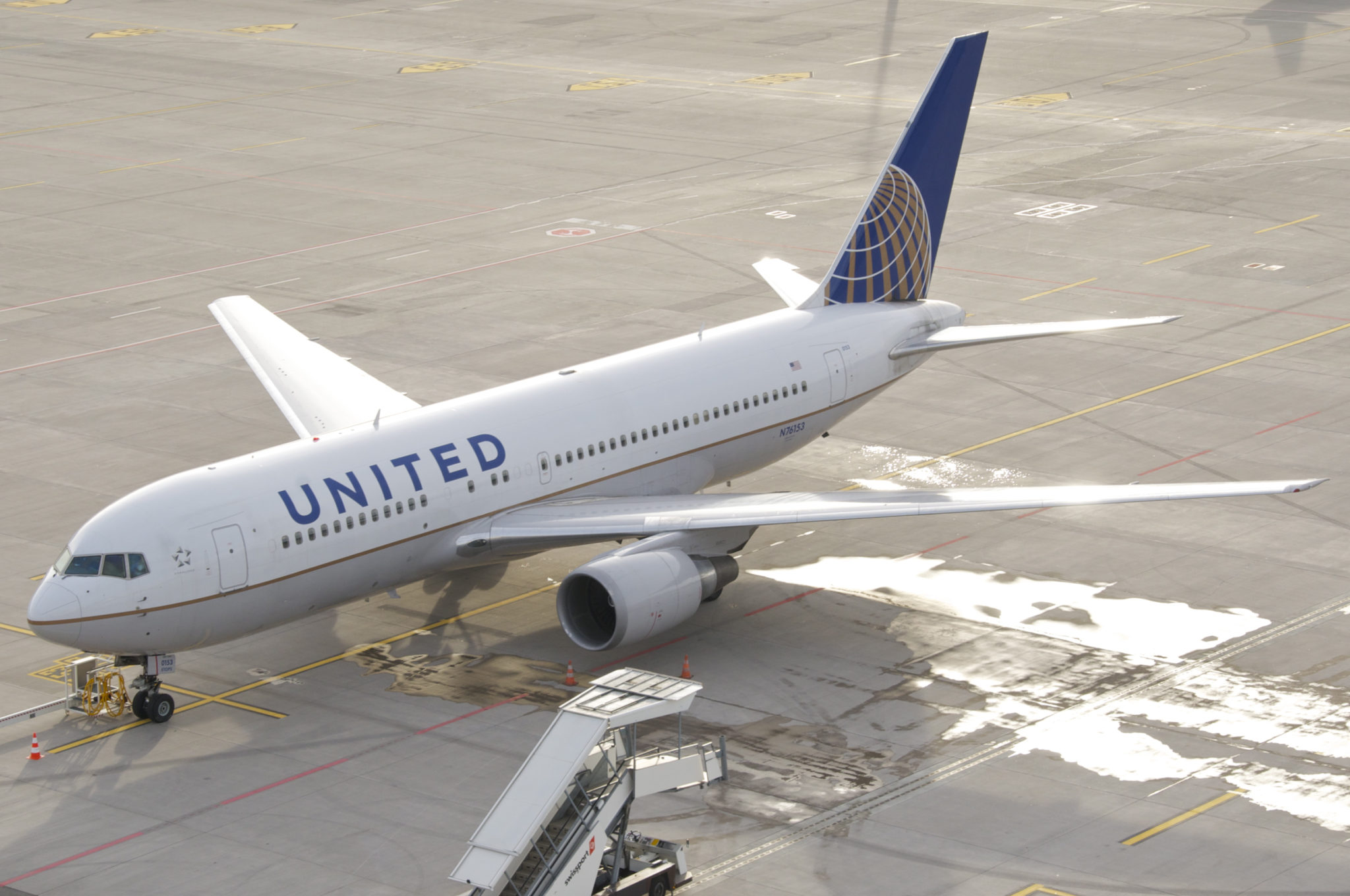
Figure 1. The NMA takes more and more the shape of a 767 replacement (A United 767-200 pictured). Source: United.
What will be the typical dimensions for an NMA fuselage and what will be passenger capacities?
Summary:
- An elliptical fuselage will force a CFRP design.
- The fuselage door configuration will be critical for cabin capacity and flexibility.
Bjorn’s Corner: Aircraft engine maintenance, Part 5

By Bjorn Fehrm
March 31, 2017, ©. Leeham Co: In the last Corner, we showed flight hour graphs for wide-body engines. Now we will deduce the market for engine overhauls from these graphs.
It will show which engines are still in engine manufacturer care, in their main maintenance cycle and in the sun-set phase.
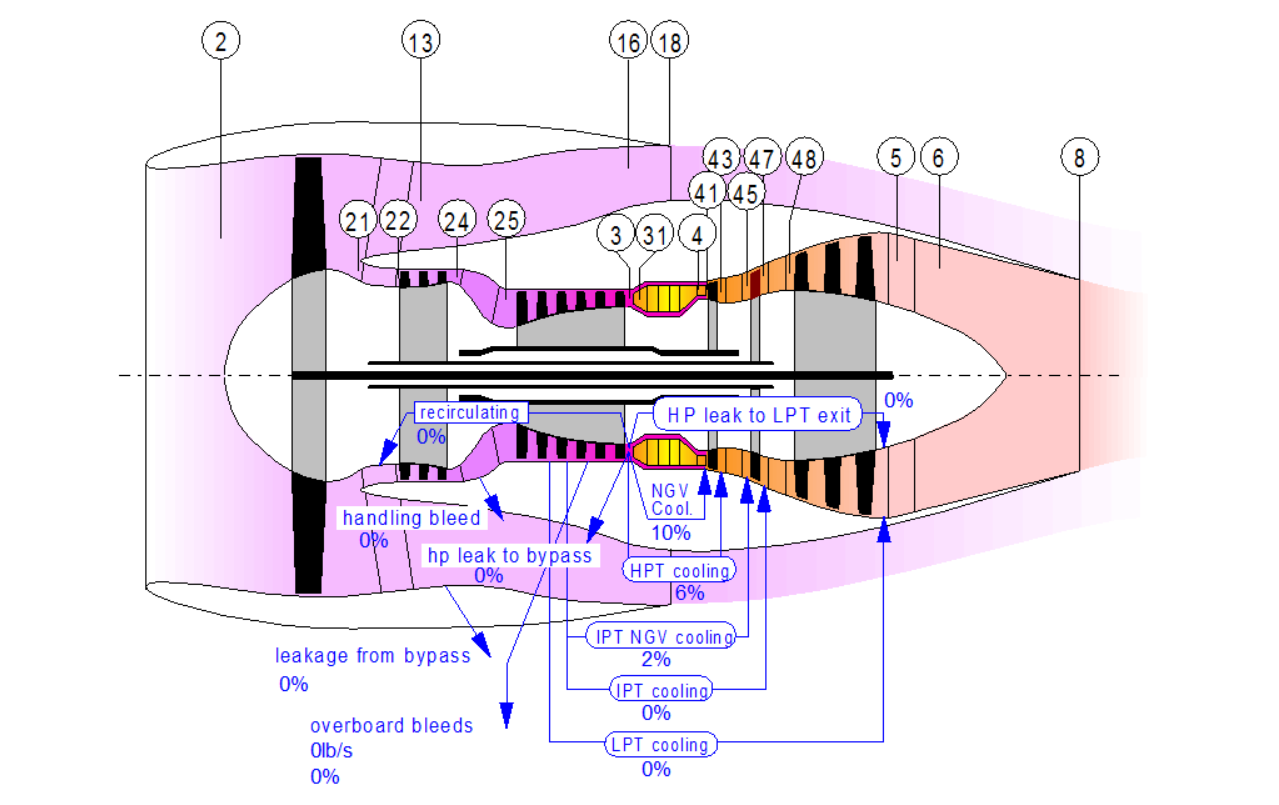
Figure 1. Principal picture of a three shaft turbofan. Source: GasTurb.
The phase the engine is in and its future flight hour development will decide the attractiveness of the engine for overhaul organizations. Read more
CSeries wrapping up London City certification
By Bjorn Fehrm
Subscription Required
Introduction
March 27, 2017, © Leeham Co.: Bombardier (BBD) CSeries did the last flights of a six-month London City Airport certification last week. The CS100, when certified for London City, will more than double the available payload/range out of the airport. In fact, it can reach New York direct with 40 business passengers on-board, something it demonstrated when it left the airport for JFK on the Saturday.

Figure 1. CS100 taking off for a validation flight at London City Airport. Source: Bombardier.
The aircraft was designed for this performance level from the outset. By designing the CSeries with engines and aerodynamics for the larger CS300, the smaller CS100 became a stellar take-off performer, providing short-field capabilities for London City and other urban airports.
Despite the design for London City, it took Bombardier six months to certify CS100 for the airport. We spoke to CSeries VP Rob Dewar about the challenges and the changes needed to the aircraft to meet the demands of London City.
Summary:
- CS100 doubles the payload-range performance out of London City Airport (LCY)
- Validation flights by SWISS pilots in the week confirmed CSeries suitability for LCY. SWISS should know; it has flown the CSeries predecessor (BAE 146) for years into London City.
- The adaptation for the airport has not degraded normal performance. CSeries performance is better than announced and brochure performance will soon see its second upgrade.
- To finish of the validation flights, BBD flew the difficult westward leg London City-New York JFK direct, with a payload representing 40 passengers in business class.
Bjorn’s Corner: Aircraft engine maintenance, Part 4
By Bjorn Fehrm
March 24, 2017, ©. Leeham Co: After covering the maintenance market for single-aisle engines, time has come for the engines used on wide-body aircraft. The engine maintenance for a wide-body engine is a bit different to the single-aisle engine. The difference is caused by the longer flight times for the wide-bodies. This makes the flight time wear a more dominant maintenance driver than it is for the single-aisle engines.
The changes in overhaul work caused by the difference in flight profiles and the lower number of engines in the market (compared to the single aisles) will affect how the overhaul market is structured and who are the dominant players.
Figure 1. Principal picture of a tri-shaft turbofan for the wide-body market. Source: GasTurb.
Could an NMA be made good enough?
By Bjorn Fehrm
Subscription Required
Introduction
March 23, 2017, © Leeham Co.: After showing there exists an NMA (New Midrange Aircraft) gap, the next question follows: Can an aircraft be made for the segment that can carve out a big enough slice to make it a worthwhile effort?
It’s a tough question. Any new aircraft will cost at least $10bn to develop for the airframe alone. To this one shall add the engine development. There exists no suitable engine for such an aircraft. To motivate the investments, the aircraft has to bring a substantial performance improvement compared to existing aircraft. Can it?
Figure 1. The NMA takes more and more the shape of a 767 replacement (A United 767-200). Source: United
We go through the key areas that can bring improvements and check if enough progress can is made until an NMA entry into service in 2024 or 2025.
Summary:
- Existing aircraft are either too little or too much aircraft to fill an NMA role.
- By careful design choices, especially for the fuselage, a new aircraft can achieve the required performance.
Major fleet decisions may not be positive for Airbus, Boeing
Pontifications is off this week.
Subscription Required
Introduction
March 20, 2017, © Leeham Co.: There are some major fleet decisions that will probably come down the pike this year at American, Delta and United airlines. Not all of them are going to be viewed positively by Airbus and Boeing.
 There is also a serious warning sign emerging from the Middle East that could have serious, negative impacts on Airbus and Boeing.
Summary
- American Airlines doesn’t want its Airbus A350-900s any more. Consolidation with US Airways appears to have made these surplus.
- Delta Air Lines, which so far eschewed any orders for the Airbus A320neos and Boeing 737 MAXes, is understood to be readying a Request for Proposals to be issued this year.
- United Airlines doesn’t want its Airbus A350-1000s any more. Picking up cheap Boeing 777-300ERs appear to have made these surplus.
- Emirates Airlines, reacting to Brexit and Donald Trump’s travel bans, is undertaking a full business review in response to a sharp drop in bookings.
Bjorn’s Corner: Aircraft engine maintenance, Part 3
By Bjorn Fehrm
March 17, 2017, ©. Leeham Co: In the last Corner, we showed graphs of the yearly flight hours for engines on single-aisle aircraft. Now we will deduce the market for engine overhauls from these graphs.
These will show which engines generate a maintenance volume that is interesting for engine overhaul companies and which engines are niche.
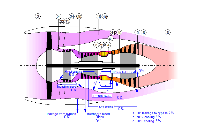
Figure 1. Principal picture of a direct drive turbofan. Source: GasTurb.
Based on the market size, we will then go through how an engine is maintained when new, mature and at end-of-life.
Bjorn’s Corner: Aircraft engines maintenance, Part 2
By Bjorn Fehrm
March 10, 2017, ©. Leeham Co: Last week we started the series how airline turbofans are maintained. We described the typical work scopes and what the intervals were for different single-aisle engines.
Before we can describe the engine maintenance market we must get a feel for the market size for different engine types.
Figure 1. Principal picture of a direct drive turbofan. Source: GasTurb.
We will start with understanding the single-aisle engine maintenance market. Read more
Engine OEMs diverge on technology for next generation
March 7, 2017, © Leeham Co.: Representatives of the four major commercial engine
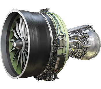
GE9X, the final engine in a decade-long engine renewal program for GE Aviation and CFM International
manufacturers have divergent views of the next round of engine development, either for the Middle of the Market/New Mid-range Airplane (NMA) or New Small Airplanes (NSA) coming in the next decade.
Officials of CFM, GE, Pratt & Whitney and Rolls-Royce appeared at the annual ISTAT conference in San Diego yesterday.
PW’s Rick Deurloo, SVP of Sales, Marketing Commercial Engines, had the added task of dealing with the highly-publicized teething issues surrounding its new Geared Turbo Fan engine on the Airbus A320neo.