Leeham News and Analysis
There's more to real news than a news release.


Bjorn’s Corner: Aircraft engine maintenance, Part 6

By Bjorn Fehrm
April 7, 2017, ©. Leeham Co: Last week’s Corner developed the overhaul shop visits per year for wide-body engines. We will now look at how the market develops around these overhaul opportunities.
How does the shop structure develop over a popular engine’s life-cycle? How much choice has an operator and when?
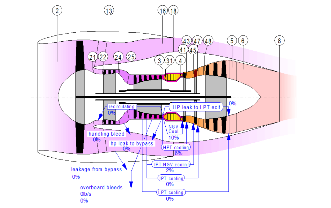
Figure 1. Principal picture of a three-shaft wide-body turbofan with station numbers. Source: GasTurb.
Bjorn’s Corner: Aircraft engine maintenance, Part 5
By Bjorn Fehrm
March 31, 2017, ©. Leeham Co: In the last Corner, we showed flight hour graphs for wide-body engines. Now we will deduce the market for engine overhauls from these graphs.
It will show which engines are still in engine manufacturer care, in their main maintenance cycle and in the sun-set phase.
Figure 1. Principal picture of a three shaft turbofan. Source: GasTurb.
The phase the engine is in and its future flight hour development will decide the attractiveness of the engine for overhaul organizations. Read more
Bjorn’s Corner: Aircraft engine maintenance, Part 4
By Bjorn Fehrm
March 24, 2017, ©. Leeham Co: After covering the maintenance market for single-aisle engines, time has come for the engines used on wide-body aircraft. The engine maintenance for a wide-body engine is a bit different to the single-aisle engine. The difference is caused by the longer flight times for the wide-bodies. This makes the flight time wear a more dominant maintenance driver than it is for the single-aisle engines.
The changes in overhaul work caused by the difference in flight profiles and the lower number of engines in the market (compared to the single aisles) will affect how the overhaul market is structured and who are the dominant players.
Figure 1. Principal picture of a tri-shaft turbofan for the wide-body market. Source: GasTurb.
Bjorn’s Corner: Aircraft engine maintenance, Part 3
By Bjorn Fehrm
March 17, 2017, ©. Leeham Co: In the last Corner, we showed graphs of the yearly flight hours for engines on single-aisle aircraft. Now we will deduce the market for engine overhauls from these graphs.
These will show which engines generate a maintenance volume that is interesting for engine overhaul companies and which engines are niche.
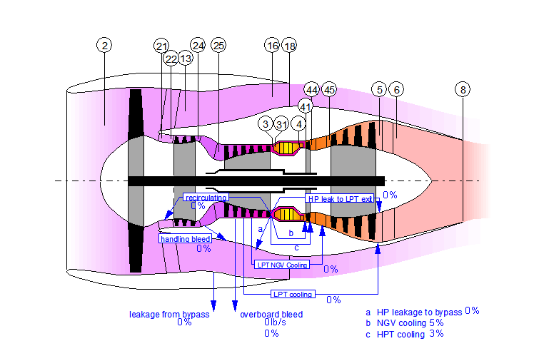
Figure 1. Principal picture of a direct drive turbofan. Source: GasTurb.
Based on the market size, we will then go through how an engine is maintained when new, mature and at end-of-life.
Bjorn’s Corner: Aircraft engines maintenance, Part 2
By Bjorn Fehrm
March 10, 2017, ©. Leeham Co: Last week we started the series how airline turbofans are maintained. We described the typical work scopes and what the intervals were for different single-aisle engines.
Before we can describe the engine maintenance market we must get a feel for the market size for different engine types.
Figure 1. Principal picture of a direct drive turbofan. Source: GasTurb.
We will start with understanding the single-aisle engine maintenance market. Read more
Engine OEMs diverge on technology for next generation
March 7, 2017, © Leeham Co.: Representatives of the four major commercial engine
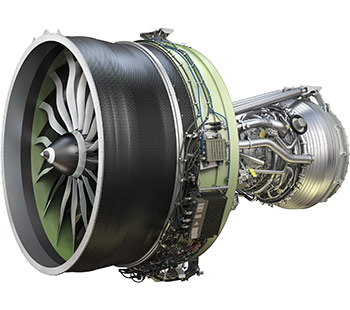
GE9X, the final engine in a decade-long engine renewal program for GE Aviation and CFM International
manufacturers have divergent views of the next round of engine development, either for the Middle of the Market/New Mid-range Airplane (NMA) or New Small Airplanes (NSA) coming in the next decade.
Officials of CFM, GE, Pratt & Whitney and Rolls-Royce appeared at the annual ISTAT conference in San Diego yesterday.
PW’s Rick Deurloo, SVP of Sales, Marketing Commercial Engines, had the added task of dealing with the highly-publicized teething issues surrounding its new Geared Turbo Fan engine on the Airbus A320neo.
Singapore 777-9 order pressures, but does not kill A380
Feb. 16, 2017, © Leeham Co.: Last week’s order by Singapore Airlines for 20 Boeing 777-9s and 19 Boeing 787-10s immediately was viewed by some as the death

Boeing 777-9.
knell for the Airbus A380.
The 777-9 order would start the final spiral down for the A380, some contend.
This overstates the case and misunderstands the nature of the order.
The A380 is in trouble, there no doubt about that. The 777-9 is putting pressure on the A380. There’s no doubt about this, either. But the contention the Singapore 777-9 order sends the A380 on a death spiral is wild fantasy.
An Airbus official appears today at the annual conference of the Pacific Northwest Aerospace Alliance (PNAA) in Lynnwood (WA). Undoubtedly, he will maintain the party line that the future of the A380 is solid. This, too, overstates the case. There can be a future for the airplane, but some major decisions must be made.
Bjorn’s Corner: Aircraft engines in operation, Part 3
By Bjorn Fehrm
February 3, 2017, ©. Leeham Co: In the last Corner, we went through how our airliner engine reacts to the different phases of flight, including what happens when we operate in a hot environment.
We also showed how engine manufacturers make a series of engines with different thrust ratings by de-rating the strongest version through the engine control computer.
Figure 1. Principal picture of a direct drive turbofan. Source: GasTurb.
We will now look deeper at how engines are controlled and why so-called flat-rating is important. Read more
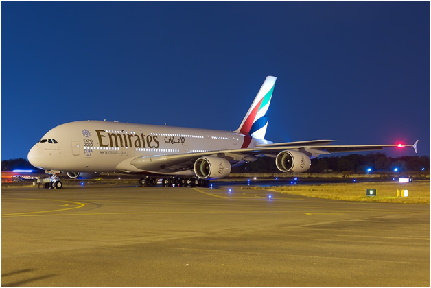
A380, from flagship to LCC mass transport
By Bjorn Fehrm
January 23, 2017, ©. Leeham Co: The Airbus A380 was introduced as the flagship aircraft for an airline’s fleet. Legacy carriers with a large long-haul network introduced the aircraft on the routes with the most traffic in the network. After an initial rush of inductions, only Emirates continued to buy the aircraft in larger numbers. The aircraft had become too large for the airlines which sought frequency over capacity at their hub airports.
Airbus and its leasing partner, Amedeo, are convinced the aircraft will have a second spring when airport congestion has grown in the next decade. Until then, both are seeking the market niches that will keep production at minimum one aircraft per month.
We sat with Amedeo’s CEO, Mark Lapidus, at the Air Finance Journal conference in Dublin to find out what market will require a new or used A380. Lapidus has spent the last two years in meetings with the world’s major airlines, discussing all aspects of operating an A380. He presented some surprises.
A380 cost analysis
Subscription Required
Introduction
Jan. 23, 2017, © Leeham Co.: In a sister article, we will describe how Airbus A380 might change from a flagship aircraft for legacy carriers to a competitive tool for long-range LCCs.
This change of the A380’s profile is based on bringing cabin densities to the levels of other long haul aircraft. We have historically made detailed operating costs studies of the A380 versus other large long-haul aircraft.
With the possible change in the aircraft’s operating profile, we decided to update the study with the A380ceo pitted against its main competitors, Boeing’s 777-300ER and 777-9. Different from the previous study, we now compared all aircraft in a higher density, two-class seating.
Summary:
- The A380neo is pushed out in time for now. Airbus has instead started a cabin density program.
- We update the study of A380 versus its main competitors to see if the cabin changes goes far enough.
- In the last study, the A380 had lower seat mile cost than 777-300ER but was beaten by the 777-9.
- We check if a denser cabin makes the A380 competitive with the 777-9